

FantomXR
-
Posts
1,035 -
Joined
-
Last visited
-
Days Won
22
Content Type
Profiles
Forums
Blogs
Gallery
Posts posted by FantomXR
-
-
I use PEC16 without issues.
-
Hi!
Yes, there is a debounce_mechanism:
SRIO debounce_cycles=<0..65535>Anyway: Improving the hardware should be better than software debouncing.
-
Just now, Antichambre said:
What is your exact needs and your real constraints for such a board? Are you sure the Wavecore can not fit your design?
I'm building a lot of keyboards with MIDIbox and space is a problem at any time. So the main reason is, to create a PCB, that has just those components on board, which are necessary for that application (including the shift registers for scanning). This would save space and cables.
Like I said: The Wavecore seems to be a huge improvement already. So I'm curious if latigid is willing to share his project ;)
Maybe you are right: I could go through all schematics of those boards which are on the market. But as you said: This is really time consuming. I took a look into the waveshare-407-schematic. This looks promising! Very few parts and a good oversight. The datasheet of the disco-board is really killing...
-
Thanks for your suggestions!
@latigid on: Your design has a big advantage: I hate those Micro-USB connectors on the DISCO-board. So this will be a huge improvement. Also it looks a bit smaller as the DISCO-board. How about the PCBs? Do you plan to upload the layout?
I designed my own breakout-board for the DISCO-board. So it has a bunch of connectors that the MIDIbox-core doesn't have. Also some regulators and another micro-sd-card slot. I'd like to take your design, make those changes and give it a try. Is there any chance to get the eagle-files from you?@Antichambre: I've read in the link you posted that you already designed an own stm32f4-PCB. Any progress on this? To be honest: I'd really like to create my own stm32f4-PCB. But I have no clue about what is needed for a minimal circuit. Your PCB looks like it has everything on board and I just need to make my modifications to it. SMD soldering is not a problem. I have a reflow oven.
We could also think of a core, that is especially made for midibox-users. I could make them in my reflow oven and sell them to others if there is any interest.
-
Hey people,
I took a look into the drivers that come with MIOS. It seems that all STM32F4xx could be supported. Is that right?
I ask because I'm looking for a smaller alternative to the DISCOVERY-board which has a big footprint. Here f.e. you can find a much smaller board with has a STM32F405 on board:http://re.reworld.eu/de/produkte/s64dil-405/index.htm
Any informations on this?
Best,
Chris -
2 hours ago, macsaif said:
Is there any script to set the midi channel for each keyboard and control it by switches?
This might be possible with using the SET ^chn command in an NGR (which again is triggered by a button / switch),.
2 hours ago, macsaif said:Also I want to make possible to switch -2, - 1, 0, +1, +2 octave transpose, is it possible to control it from some inputs?
Same here! Please see here:
-
5 hours ago, Psykhaze said:
is it possible to have separated matrixes with the SRIO ? the special design i have in mind for example is having : [DIO-MATRIX]----[DINX*]----[DIO-MATRIX] modules linked together , like if for whatever routing reasons you have to handle encoders in middle of two matrixes of switches/ LEDs to stay modular for example. Any would say that the most easy would be to do [DIO-MATRIX]---[DIO-MATRIX]---[DINX*] to keep the matrix united but i wanted to know if the mentionned design might work?
Why should it not? If you add some DINX between the two DIO-modules you just have to change the values for the shift-registers in the NGC-file.
-
Hi Frank,
yes. That is possible. You can achieve that by using a NGR-script, that sets break_is_make on. This script you need to trigger with the switch.
-
Hm... I'm using NG in keyboards for a few years now and as far as I remember I never had the issue, that notes are not being played. I enable make_debounce on my keyboards. Without that sometimes note-off is not being send (IIRC).
As NG does not support 3-contact-keybeds at the moment it needs both contacts to be opened before sending the next note-on. Without both switches opened NG can not calculate the velocity so it's not being send.
If "break_is_make on" works for you, it's quite clear, because break_is_make doesn't wait for both switches to be released.
-
My tests with NG vs KB had the result that no matter what I change in the official NG-app, I'll never get those fine velocity steps, that KB gives. So I created my own NG app and kicked out all of the functions, I do not need. There is a thread about it in this forum. Just use the search engine and you'll find it quick.
Anyway: I still feel, that KB outputs more velocity values as my NG does still. So I think it depends on your needs.
Btw: please be aware, that there is no octave shift function (regarding if NG or KB) yet
-
Yes @Zam you are right. I had issues with those LEDs. But since I use a separate PSU for the LEDs the problem is gone! ;-) Well, I'm still not able to run the faders in 11bit because of jitter (regardless if the LEDs are connected or not) but I really don't need that. 7bit is sufficient.... and thats another topic ;-)
I also made a design-mistake: The VDD-traces on the LED-PCBs are way too thin. I used about 0,6mm which might not be enough for this current. I expect a current of above 2A when changing the color for the LEDs. Of course I never run them at full brightness! Then they would draw MUCH more.
But yes: If you think we would be able to make something "better", than start another topic. I'm happy to help! (but I'm on vacation from tomorrow on ;-) )
-
Like I wrote somewhere on the forum before: if you want to connect an 61key Fatar keybed to DIO matrix you do not (!) need any kind of adapter PCB. Just use two 16pin ribbon cables and twist them by 180 degrees.
-
 1
1
-
-
So I now did some changes: I added an 68pF (I had this in stock... I had no other value available without visiting the next electronic shop) ceramic cap between SCLK and GND at the very end of the OLED-Chain.
I also added a 10uF on the IDC connector of the OLEDs between VDD and GND.
I also added a 100uF on the WS2812B connector.
I checked again the wiring and it seemed that the OLEDs were connected to the same power supply as the LEDs. So I changed that! The OLEDs are now powered from a separate PSU.
I didn't have time to put the MeanWell PSU into the device... this is a lot of work... I'll do next year ;-)
I'll keep testing the device in the next days / weeks and report back!
Thanks!! -
I'd like to help but I really don't understand what the problem is. What is connected to where? How many keys? Which keybed?
-
Hi @Zam,
do you have a photo of the inside of the Juno 60? I'd like to see how it looks like with the Al foil ;-)
Thanks!
Best,
Chris -
Dear @Zam,
you may be right. But I think, that wooden housings are way more complicated to build in a mass production than metal. This is also a reason why you do not find them on the market.
Adding an Cu or Al foil is a good idea!Thanks! The LEDs are WS2812B ;-)
-
Btw: here you can see it in action. The video was made in the same room where also the problems occur. Today it worked the whole day flawlessly. Very strange, that it sometimes works perfect and another day it starts to freak out after 3min.
https://www.dropbox.com/s/7ajek30k9qopmlf/Video%2004.12.17%2C%2022%2051%2016.mp4?dl=0
-
It's 19V DC.
I didn't use SMPS! This was a translation mistake ... I used those modules (LM2596) after the 19V:
Anyway: I think I'll replace all of those (3 of them are build in the housing because I thought I also need 3.3V and 12V) by a single 5V 10A AC-DC converter from MeanWell. This sounds much more convenient and professional. Also the specs look better.
-
Dear zam,
thanks for your reply. I understand your concerns. The whole case is made from wood and I don't have any metal parts inside yet. I'm aware of the fact, that all metal parts should be connected to "earth".
The power supply is a standard notebook power supply, which of course is connected to earth on the primary side. On the secondary side there is no connection to "earth". The 19V from that supply goes into SMPS, which is where I get the 5V from.
With that said: I'm familiar with GND and "earth" in the basics. So I made everything as safe as possible.
If I got you right you suggest to add a connection from the power supply secondary side (-) to "earth", correct? If I talk about GND I mean secondary in any case. Sorry to be unclear.
@peter: ahh! Got you. Thanks! Yes! I use 4-wire SPI.
-
It's a wooden case...
Do I have to connect GND to "earth"?
-
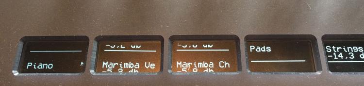
So guys.... yesterday I spent a lot of time in front of my controller. The room, where the controller is placed at the moment, has a carpet. I noticed, that I get a little shock after while walking through the room when touching metal. I was curious too see if it has an impact to my controller. So I walked through the room and after that touched the encoders, which are directly above the OLEDs. And guess what? The whole electronic became unstable: The OLEDs were freaking out (see pic above) and other illuminated buttons which are connected to the electronic went dark for a few milliseconds. I use those buttons to change the colors of my WS2812 LEDs and it seemed that some of these buttons got triggered, because the color of the LEDs were changing too.
It seems that I have an ESD problem here. Is there anything I can do to protect my electronic? BTW: The caps of my encoders are made from aluminum, but they sit on a plastic shaft. So I'm not sure how the "shock" made it into the electronic. (//edit: I don't think that I can connect GND to earth on my AC input?)The first thing I'll add is the suggested cap between RST and GND.
The second thing is a larger cap between VDD and VSS at the ribbon connector.
For the next PCB revision I'll probably change the 10pin IDC to a 14pin / 16pin (or just add another 2pin header and use stronger wires) and add a second VDD and VSS wire for a stronger connection.
Another change I'll make is adding another power supply to the unit. I thought about MeanWell LRS-50-5 which comes with 10A at 5V. I hope to get off the ripple that is inducted by the switching regulators which are working inside the case at the moment.Also for next revision maybe I can add the buffers to the PCB with Andys help... we will see ;-)
Thanks for now! I'll report back.
-
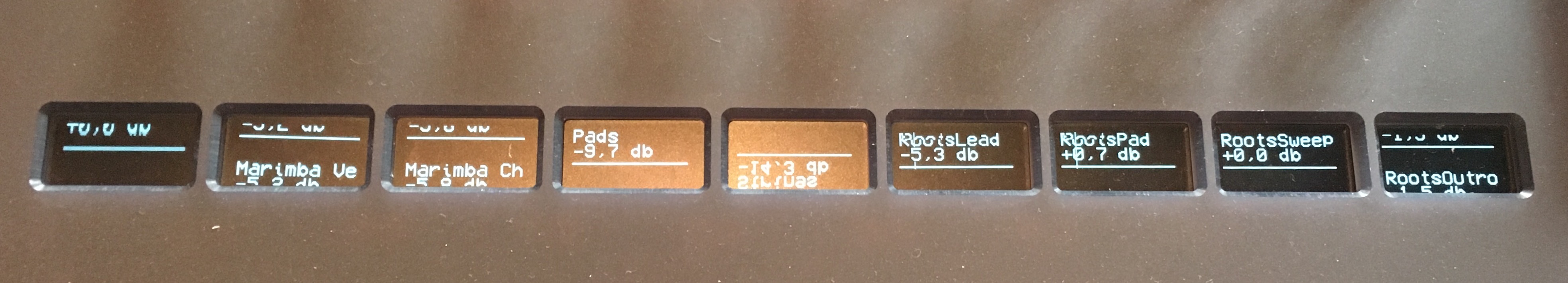
It goes crazy!

-
Hey people,
@Antichambre: I can't follow you regarding the decoupling cap. It should be in the right place....adding the cap to the supply-connector seems useful! Will do!
I can't do too many changes at the moment to the electronic. But to try it out I killed the external power supply and power the core now via USB. As you can see I have the same problems (see pic).
I hope I can do those changes we discussed here on tuesday...
-
Hey,
thanks for sharing!
In my design I don't have space for such a board and it would be overkill because I do not drive so many OLEDs.Anyway: I'll try Peters way first and report back!
Thanks so much for your help!

Midibox_NG and kb_transpose
in MIDIbox NG
Posted
Easy task! Just create two EVENT_KBs with different ids but same hw_ids and set them to different channels.
Regarding your second question: I think TK implemented a Learn-function a while ago. Maybe this works with KBs too. Search here for "learn":
http://ucapps.de/midibox_ng_manual_ngc.html