

FantomXR
-
Posts
1,035 -
Joined
-
Last visited
-
Days Won
22
Content Type
Profiles
Forums
Blogs
Gallery
Posts posted by FantomXR
-
-
Just now, goyousalukis said:
I don't know if this is the case for NG
No, it's not. I use SD-cards with 16GB and more without any problems.
-
 1
1
-
-
14 hours ago, macsaif said:
What kind of SD card do you recommend? Are there any limitations or recommendations: speed, capacity, manufacturer?
No, anything should work. NGC-files are very small. So 12MB would be sufficient, but you won't be able to find a SD-card like this. Just take what you have or what you can get.
-
23 minutes ago, macsaif said:
Is it possible to upload. Ngc files without connected SD card?
Of course not. The SD-card saves the NGC-files.
You can find all parameters of a NGC-file on this page:
-
Sure! What kind of tipps do you need?
Best,
Chris -
No.
Here you can find a description of all commands:
http://ucapps.de/midibox_kb.html -
You have to try it out by yourself. Velocity-response is highly subjective.
Why don't you just upload NG and try it out? I think you can do this without SD-card because all terminal-commands that work on KB will work on NG too (but won't be stored after shut down).
-
On 10.3.2018 at 11:38 PM, macsaif said:
only pitchwheel needs an analogue correction or calibration in midibox ng
Your values that you will get after software-calibration in NG will not be sufficient for pitchbend. Pitchbend is high-resolution MIDI with 11 or 12bit. In my experience there is no way to get this smoothly running without a hardware calibration. I posted a link above where duggle made some examples.
To explain the difference between software- and hardware-calibration:
Depending on the ADC you use, you need a fullscale of 0-3.3V or 0-5.0V to get a nice pitchbend-signal. If I read your post correctly your potentiometer reads 0.5V-2.5V. That results in a fullrange of 0-1.5V.
With the pinrange-calibration NG offers you can now tell (=offset) the MIDIbox, that it should take 0.5V as lowest analog voltage and 2.5V as highest analog voltage. But anyway: You still have only 1.5V which is less than half NG expects.If you do a hardware-calibration you will use an IC and some resistors to offset AND scale your range 0.5V - 2.5V to 0V-3.3V / 5V so the potentiometer outputs fullscale! That gives NG the full range and you won't end up with jittering values or a bad resolution.
In short: Software can only set an offset of an analog signal but it can not scale it. -
Do you have a photo of your wiring?
Make sure that the ribbon cable that goes from Core to the first DIO is twisted while the ribbon cable from 1st DIO to 2nd DIO is straight.
-
Just now, macsaif said:
set kb 2 optimized off
set kb 2 dout_sr1 3
set kb 2 dout_sr1 3
set kb 2 din_sr1 3
set kb 2 din_sr2 4should be
set kb 2 optimized off set kb 2 dout_sr1 3 set kb 2 dout_sr2 4 set kb 2 din_sr1 3
set kb 2 din_sr2 4
-
Where did you buy the 73 keybed? I was never able to get the 73 TP/8O running. At least on my test-keybed it seems that the scanning is totally different and I never had the courage to dive into this.
Anyway: I have a 76key hammeraction and also a TP/8SK with 73 keys which both are working fine. The TP/8SK has reversed diodes so you have to adapt the hardware (jumper) and software (din_inverted).
And I don't understand this:
Just now, macsaif said:It is working, so there should be some other problem
Is it working or not?
-
On the 76key the pins are swapped. So T0-T7 is the lower row and break / make adapter upper.
I have an adapter made for this. If you are interested I can send you the design.
-
Hi!
1.) Try to set make_debounce=1
2.) Those values depend on your own liking. It's not that hard to find out the values that fits your playing.
3.) Yes. But not in MB_KB. In NG you can define maps.
4.) Same here. In NG it's easier. Also if you do not calibrate the potentiometer on the hardwareside you won't get the full resolution. You need to scale and offset the output of the potentiometer to the full range of your ADC. Look here:
5.) Nothing special has to be done. But you need an adapter. You can not connect the 76 / 73 key straight to the DIO matrix as you can do with the 61.
-
Hey!
No. The spacing of the encoders is 29mm which is my standard grid. I use OLEDs with the same spacing.
-
@Antichambre: You can order them at chia shin. But MOQ is 1000pc.
-
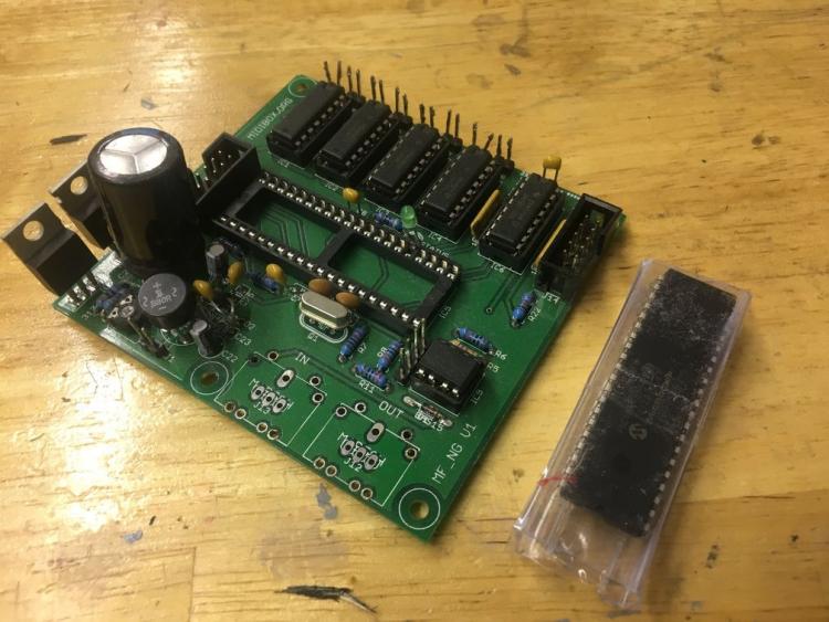
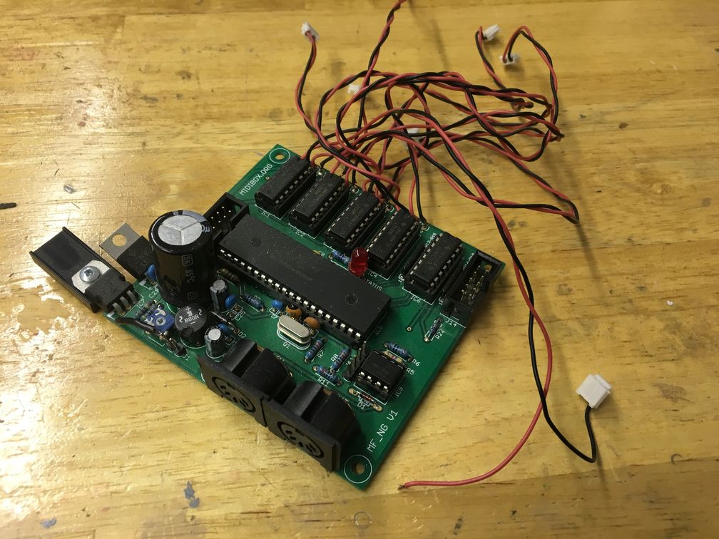
Hey people,
I'd like to get rid of some stuff I do not need anymore. Some PCBs are assembled already. Here we go:
LPC17-Core-PCB:
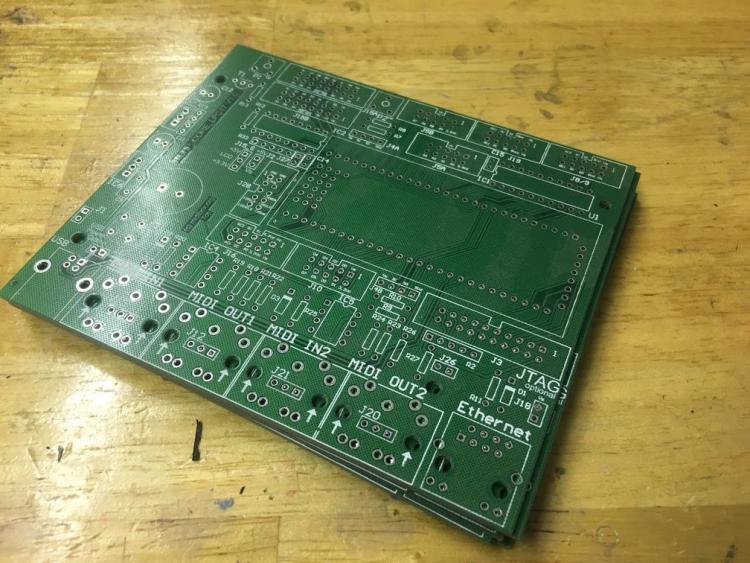
Price: 5€ / pc.
LPC1769-uC Rev. C:

Price: 15€
Encoder-PCB (shiftregisters & resistors are SMD (and not mounted) but easy to solder with a good soldering iron):
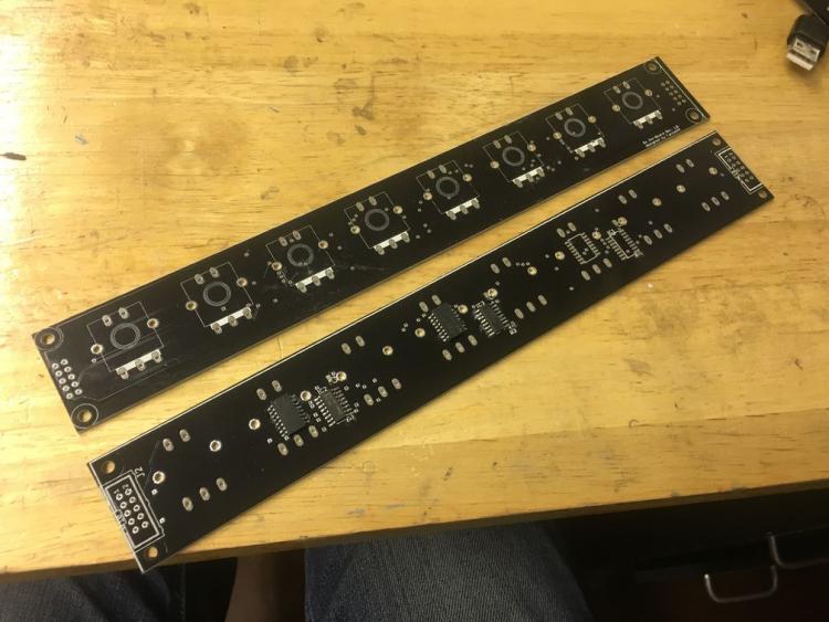
Price: 5€ / pc.
Encoder-PCB (all parts mounted. The first encoder is detented. I'll remove the caps):
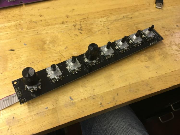
Price: 15€
I'm in Germany.
Best,
Chris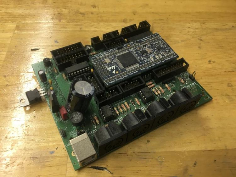

-
@Zam: Just a quick note on this: I tested several things on my PCBs but I was not able to get rid off these value-jumping-issues when changing the colors on my WS2812B. After researching I found a little chip called MCP1541 from microchip. This generates a super stable reference voltage for the MCP3208 out of 5V. Even out of the noisy USB-5V. And this solved all problems. Such a great IC. Also very low component count. MCP1541 + 2 caps and you are done.
-
How many do you need? I just received 40pc.
-
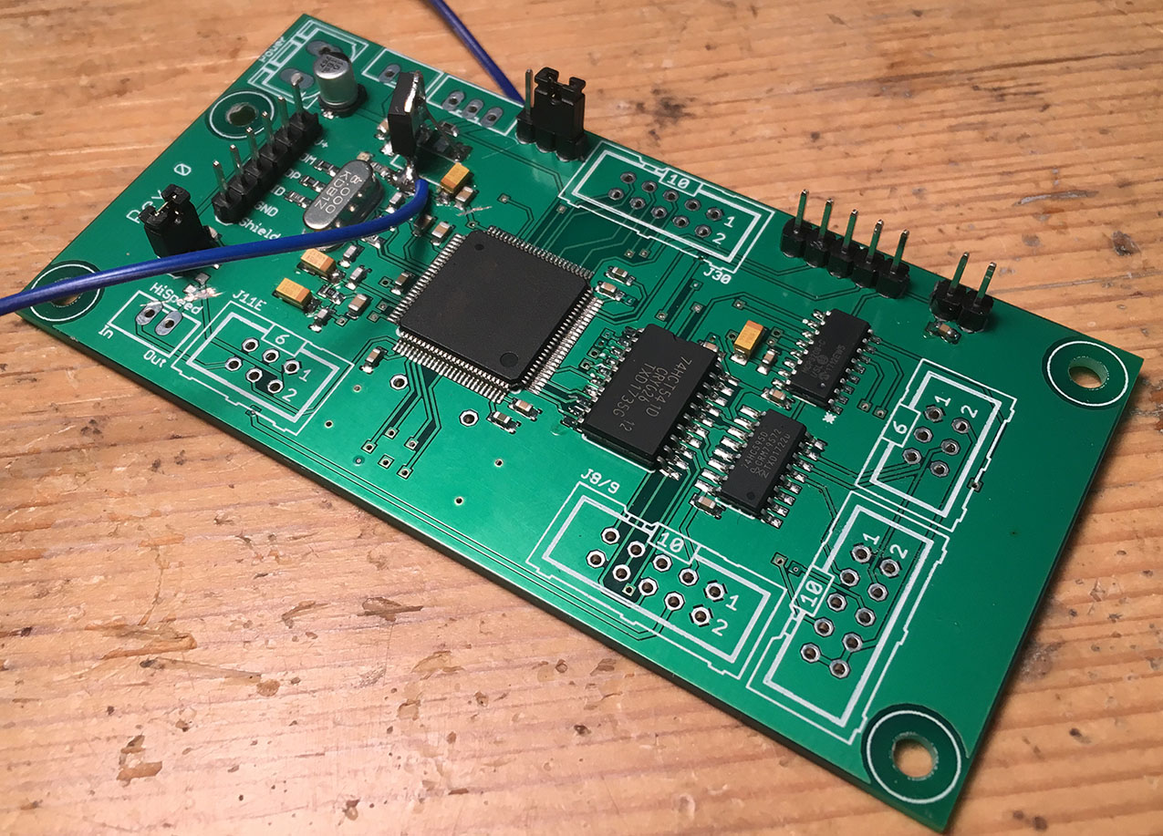
Hey people,
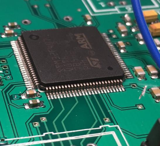
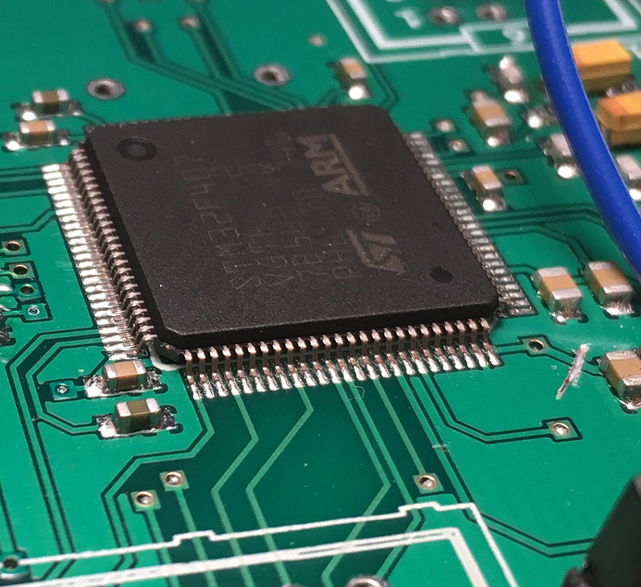
since I'd like to be independent from the availability of the STM32F4-discovery board I started designing my own board, which has an STM32F407VGT6 on board. Its an LFQP 100 package, so not easy to solder. I have a reflow oven and the first PCB I made seems to work fine.
The PCB has very few components. This was just a quick test board to see if the basic circuit of the STM32F4 is working. It's basically just the STM itself and it's components like caps and crystal. Also there is a 3.3V regulator (based on 1117 but will change to TC2117) to power the uC. I added a pinheader for USB connection (on the very left), a pinheader for SWD to flash the bootloader and a reset-header.
On the right you see the HCT541, which connects to J8/9 (tested: works fine). Also I added an MCP3208 and HC595 for an AINSER64-like-analog-scanning.
On the bottom of the PCB there is a MicroSD-slot.
No changes in the firmware are needed to use this. The only thing one need to do is flashing the bootloader the first time. @latigid on made a nice "how-to": http://wiki.midibox.org/doku.php?id=wcore After that you can use the MIOS as is.
So, why I'm telling you this?
This core is already very specific for my applications. But if you are interested I could upload the minimal circuit for the STM32F4 to work and you could add all headers and components that YOU need by yourself. So in theory you could recreate the original MIDIbox core but you should end up with a much smaller footprint (especially regarding height).
If you need assistance regarding soldering the STM32F4 I can offer to reflow-solder it for you.
I'll clean up my circuit and upload it the next days!Best,
Chris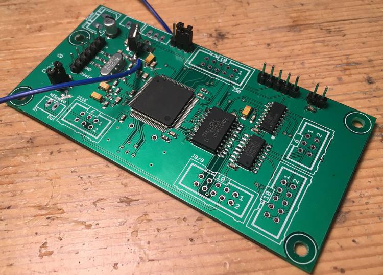
-
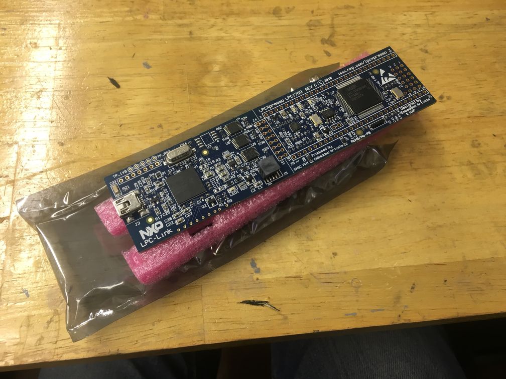
@Alasdair Moon The discovery board is now available again on mouser.
-
1
-
-
My prototype-PCB arrived yesterday. I set up my reflow oven and gave it a go. I'm very happy with the result. LQFP100 is really small. But it's working! Apart from some changes I needed to make on the 3.3V power supply, it seems that I have the minimal circuit working. :-)


-
I just created a design for a core by myself and ordered it. It's downstripped (has just J8/9 + MicroSD-card reader on board) because I want to test the basic functionality of the circuit first. I'll keep you posted if it runs fine :-) If the design works, it can be easily extended to other people needs.
-
Hey people,
just a short question: Is it possible to replace the SD-Card with another kind of memory f.e. FRAM?
Thanks,
Chris -
@Alasdair Moon: Sorry! You are right... damn it!
But yeah, looks like latigid on seems to have a solution for that.
-
1
-
-


Understanding SysEx-handling and EVENT_RECEIVERS
in MIDIbox NG
Posted · Edited by FantomXR
Hey people,
my controller has 9 OLEDs which I want to address via SysEx, which works good. Here is the code:
EVENT_RECEIVER id=1 type=SysEx stream="0xf0 0x00 0x31 0x00 ^txt" label=&a lcd_pos=1:1:1
EVENT_RECEIVER id=2 type=SysEx stream="0xf0 0x00 0x32 0x00 ^txt" label=&a lcd_pos=2:1:1
etc.
Each OLED has it's own ID (0x31, 0x32, etc.).
What I now try to change is the stream that the OLEDs listen to. So I set up another set of receivers:
EVENT_RECEIVER id=11 type=SysEx stream="0xf0 0x00 0x41 0x00 ^txt" label=&a lcd_pos=1:1:1
EVENT_RECEIVER id=12 type=SysEx stream="0xf0 0x00 0x42 0x00 ^txt" label=&a lcd_pos=2:1:1
etc.
I use some buttons to "set_active" the different receivers. So the NGR reads:
if ^section == 1
set_active (id)RECEIVER:1   1
set_active (id)RECEIVER:2   1
set_active (id)RECEIVER:11   0
set_active (id)RECEIVER:12   0
exit
endif

if ^section == 2
set_active (id)RECEIVER:1   0
set_active (id)RECEIVER:2   0
set_active (id)RECEIVER:11   1
set_active (id)RECEIVER:12   1
exit
endif
I'd expect that with this code I can change the stream... but I can't. They are listening to all streams at the same time no matter if I "set_active" those receivers or not.
I thought that it might be related to the receivers. So I changed them out with EVENT_LEDs but same here. I can not achieve, to switch between those two SysEx-streams.
I also tried the "set_lock" command.... but that was also not working. I also tried button the receivers in different banks and change the banks with the buttons => no success.
So... what do I overlook? Is there any solution for my problem?
Thanks,
Chris