FantomXR
-
Posts
1,035 -
Joined
-
Last visited
-
Days Won
22
Content Type
Profiles
Forums
Blogs
Gallery
Everything posted by FantomXR
-
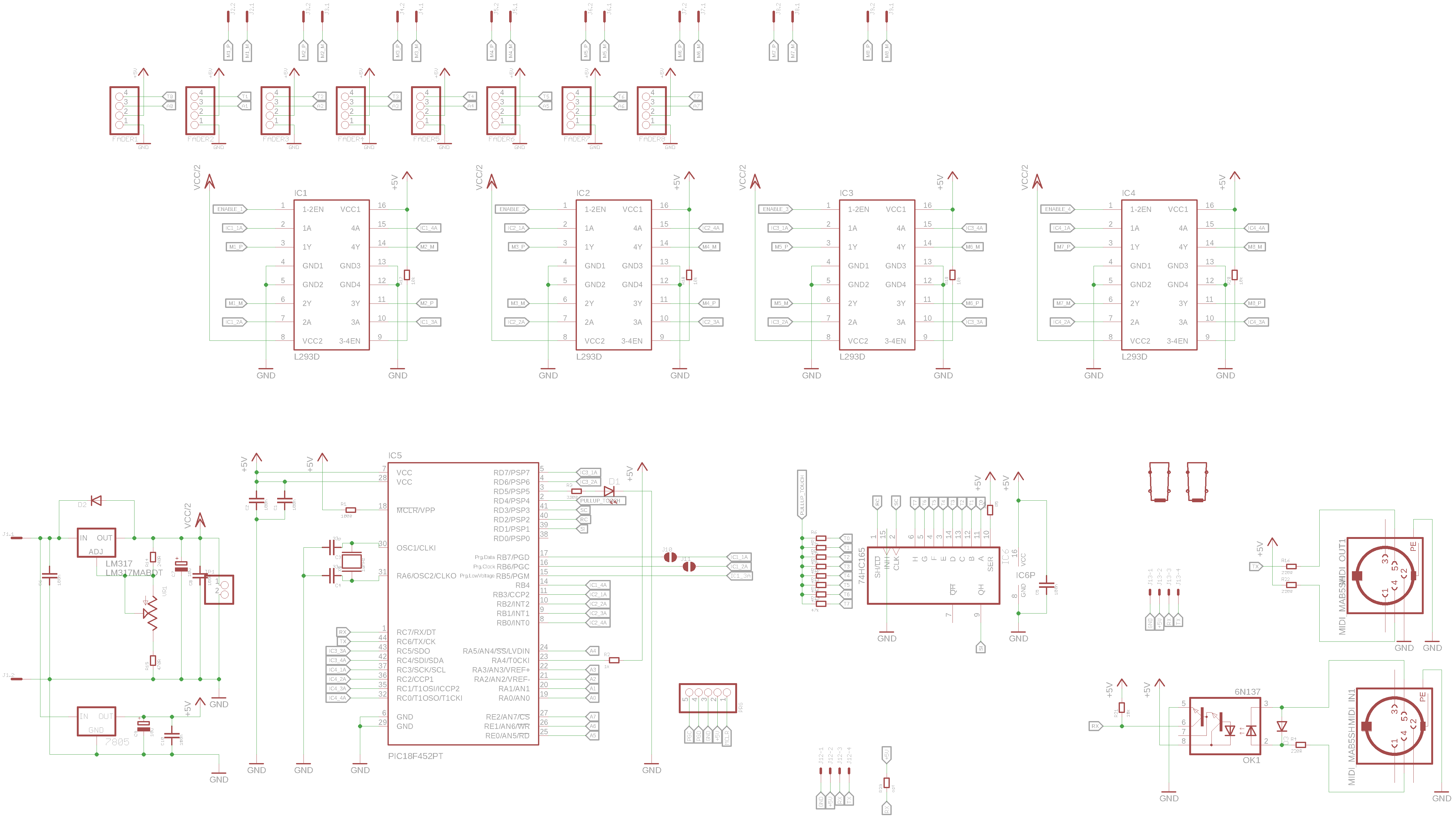
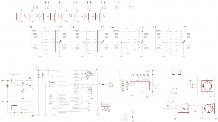
Hey people, I have a problem and I hope you can help me. I've created a PCB based on MF_NG. Schematic and layout see here: I have a PicKit3 to program the 18F4520. I use the MBLAP X to flash the bootstrap to the PIC. The programming seems to work fine. I don't get any error messages. As stated on the MIOS Troubleshooting page there seems to be a problem with the ID when working with MBLAP. See here (bottom): http://ucapps.de/howto_debug_midi.html So I also flashed the bootstrap-workaround which also ran fine. If I now connect the MF_NG via MIDI to a core, I get this error message: [395386.494] [MIOS32_MIDI_Receive_Handler] Timeout on port 0x20 Do you know what that could cause?! Best, Chris
-
See it in action here: https://www.dropbox.com/s/c9c0jklz28nhe2r/VID_20200407_105633.mp4?dl=0
-
.jpg.4f4b75bf80d51a461ceb630e87cce62a.jpg) See it in action here: https://www.dropbox.com/s/c9c0jklz28nhe2r/VID_20200407_105633.mp4?dl=0
See it in action here: https://www.dropbox.com/s/c9c0jklz28nhe2r/VID_20200407_105633.mp4?dl=0 -
.jpg.28ca571d1b3d896401f2b9318551b3a3.jpg)
From the album: MIDIBox Trellis
-
From the album: MIDIBox Trellis
-
.jpg.c3125ea265169fac12f6f6b98de969b1.jpg)
From the album: MIDIBox Trellis
-
.jpg.cb9bb48eda1104df872fc6a08d760812.jpg)
From the album: MIDIBox Trellis
-
Done! Works great. :-) So, is anybody in? It's cheap... It's $8 per PCB and $12 if you want me to add the SMD parts (except the LEDs. They are mounted by the factory). Let's see if there is interest...
.thumb.jpg.4711a5478d7a1f8a2ccdd60149756cfe.jpg)
.thumb.jpg.7d698f258910568ee2723301c7a34cbd.jpg)
-
Here are the PCBs. I will do some tests tomorrow and let you know. I also have done a rerouting of the whole thing to make it cleaner. Looks good so far.
.thumb.jpg.7b30b7324426a2b6ccff378675efa6f6.jpg)
.thumb.jpg.9d8aae35a00f4973224aba5b7b672da7.jpg)
-
Hi, I want my midibox to trigger the value of a potentiometer and send it out on startup. The NGR is as follows: if ^section == 0 trigger AINSER:1 endif The problem is that it sends zero. I first need to move the potentiometer. After that the trigger-function works well. Any solution on this? Thanks, Chris
-
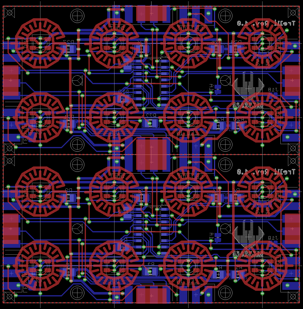
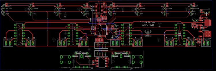
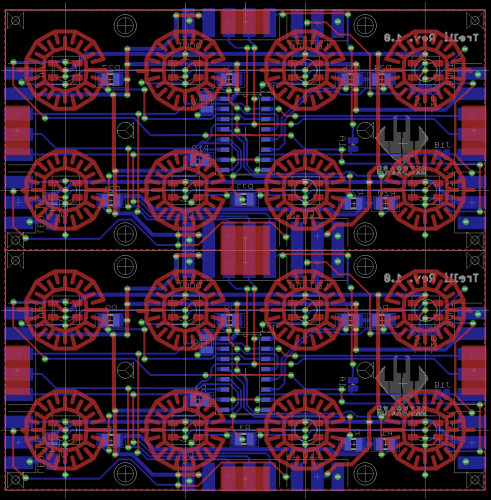
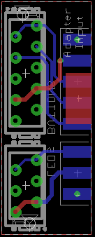
Hey people, I was looking for cheap buttons that have an integrated RGB-LED. I was searching the internet but couldn't find anything affordable. So I looked for alternatives. I found Sparklefuns Button-Pads. They look great, but for me they are too big (15x15mm). So Adafruit has similar soft-buttons called "Trellis". They are smaller (10x10mm). I downloaded their eagle-library and adapted it to my needs. The layout was made for 3mm single-color LEDs. You can find videos of it. They look already great. But wouldn't it be even more fun if we could add RGB LED? So I did. I added WS2812 LEDs underneath each button in 3535 footprint. I needed to change the pad-layout a bit to make them fit. To make it short: I made a layout, that has a HC165 on Board. The PCB is made for 4x4 Adafruit Elastomer but you could split it to get two single Boards with 4x2 each. You'd just have to set the correct solder-jumpers to make it work. Here is a picture of the layout: So if you want to use the upper 8 and the lower eight you have to bridge J1A and J2A and leave J1B and J2B open. If you want to break it and connect another of those boards to the right, you have to bridge J1B and J2B and leave the other two open. I just noticed it misses one jumper. If you want to add a board to the right, you now need to manually solder a wire from the input of J1B at the top to the output of J1B at the bottom. This needs to be changed in the next revision. It was necessary to use SMD parts for the whole design to make it fit. The connection of the boards is made through edge-SMD-pads like in the original design. To make it more stable there are not only connectors for the digital signals on the bottom, but also some bigger pads on the top. This should give it enough strength. I also made a adapter board, to connect to my core. Of course I could design another adapter board to fit the midibox connector-pinout. So I've just ordered that. I hope to received it in two weeks or so. SMT placement of the LEDs is done by the factory. The SMD parts on the back have to be placed by oneself. It's not a big deal since I used 0805 parts which can be perfectly soldered by hand. Also the HC165 is SOIC-16, which is also not that hard to solder with a good soldering iron. In case everything is working well I'd set up a bulk order if you are interested in those boards. So, if you are in, just let me know. I'll keep you posted. Stay healthy! Best, Chris
-
So meanwhile: is it worth replacing the PIC with the ESP? I'm designing a PCB for MF NG by myself. So if the PIC is outdated I'd upgrade to an ESP up front.
-
Great improvement! Thanks!
-
Alright. PCBs in the making. I'll hopefully receive them soon. I'll post the results.
-
I'm happy to help! :-)
-
I've made the PCBs by myself. I have designed a core especially for keyboard application with four pedals, midi I/o and connectors for wheels and aftertouch. If you are interested, drop me a PM. I'm in Germany as well. Best Chris
-
Check bourns encoder. You can find their stuff in mouser. And mouser has a pretty good filter / search engine.
-
I think I'll try to add capacitors to pins A and B since this is the fastest fix I could do. In the long run I'll change the layout, adding caps to ground and two 10k resistors as in the datasheet + 74HC14 to create nice and sharp results.
-
Well that is due to a different pinout if STEC12 and 16. On 12 the C terminal is in the middle while it's on the outside on 16 iirc. I'll check again and report back.
-
Hm, thanks for your help. Detented5 seems to work best. But not perfect though. Still it's jumping from now to then. But there must be some kind of code where those detent-modes are defined. And I can't find it.
-
I just see that MIOS Studio gives me an error message: [1416035.046] [MBNG_FILE_C:303] ERROR: invalid pins for ENC n=9 ... pins=5 [1416035.046] [MBNG_FILE_C:303] (expecting 0:1, 1:0, 2:3, 3:2, 4:5, 5:4, 6:7 or 7:6) I thought that this isn't relevant. So it seems I need to change the wiring :-( btw.: @TK. I can not find the code for the different detented-types in the firmware. In which file are they defined? I ask because it seems that my encoders don't work properly. I use PEC11L from Bourns: https://www.bourns.com/PDFs/pec11l.pdf I use them in relative mode. CW 1, CCW 127. When turning fast CW I also get 127 from now to then. So it seems to bounce...
-
Hey people, I have a strange problem. I have a PCB with 9 encoders. This PCB is connected to another PCB with 27 switches. In total there are 8 SR. 4 on the button-PCB and 4 on the encoder PCB. Everything works fine except the very last encoder. The encoder is connected to pin4 and pin5 of the HC165. MIOS Studio shows fine that it toggles input 62 and 63 and depending on the direction the encoder is moved, either 62 or 63 will get triggered first. So this seems to be correct. In the NGC I wrote ENC n=9 sr=8 pins=6:5 type=detented1 But for some reason NG doesn't take those events as encoder events. This is the output of the terminal: [1406781.497] MBNG_DIN_NotifyToggle(62, 1) [1406781.497] No event assigned to BUTTON hw_id=62 [1406781.503] MBNG_DIN_NotifyToggle(63, 1) [1406781.503] No event assigned to BUTTON hw_id=63 [1406781.654] MBNG_DIN_NotifyToggle(62, 0) [1406781.654] No event assigned to BUTTON hw_id=62 [1406781.662] MBNG_DIN_NotifyToggle(63, 0) [1406781.662] No event assigned to BUTTON hw_id=63 But it should like this (just with another id though): [1406866.814] MBNG_ENC_NotifyChange(7, 1) [1406866.814] No event assigned to ENC hw_id=7 [1406867.121] MBNG_ENC_NotifyChange(7, 1) [1406867.121] No event assigned to ENC hw_id=7 [1406867.446] MBNG_ENC_NotifyChange(7, 1) [1406867.446] No event assigned to ENC hw_id=7 [1406867.747] MBNG_ENC_NotifyChange(7, 1) [1406867.747] No event assigned to ENC hw_id=7 Any ideas? I use the stock NG-firmware for this test. I've also tested to set pins=6:5 to all another combination like 4:5, 6:7, etc. But none of them works. Thank you very much! Best, Chris
-
Totally possible. I do the same with Cantabile.
-
Again: look at the MAP feature. This exactly what you need. Set a map as range with range=Map1 and create a map with the desired values underneath it. See this example: https://github.com/midibox/mios32/blob/master/apps/controllers/midibox_ng_v1/cfg/tests/mapbtn.ngc
-
LRE 4x1 breakable RGB LED-Ring/Rotary-Encoder PCB bulk order
FantomXR replied to weasel's topic in Bulk Orders
Awesome! :-D