Phatline
-
Posts
1,285 -
Joined
-
Last visited
-
Days Won
72
Content Type
Profiles
Forums
Blogs
Gallery
Everything posted by Phatline
-

TR606 CY+HH Kicad Shematic (Capacitor labeling on old shematics)
Phatline replied to Phatline's topic in Miscellaneous
yes but the slot should be mooved to 90° (standing) -
TR606 CY+HH Kicad Shematic (Capacitor labeling on old shematics)
Phatline replied to Phatline's topic in Miscellaneous
agree with SD and BD Plugs and Gain. i would preefer Trigger LED located near Decay Pots (because the trigger is a envelope thing) individual outs > ok > so we need special plugs, which cut the conection to the mix bus - i know that most 6,3er Plugs can handle that, do you a 3,5er plug which can handle this? -
TR606 CY+HH Kicad Shematic (Capacitor labeling on old shematics)
Phatline replied to Phatline's topic in Miscellaneous
@Psykhaze here is the list of parameters for the HH+CY Frontpanel, maybe add 3 trigger LEDs?
-
New Topics in MBHP>Basics section of the wiki
Phatline replied to Psykhaze's topic in MIDIbox Documentation Project
ok make sense. its acts then lika a analog "thermostat" -
Bongo Triggers > velocity > piezzo electrete > ain trigger >
Phatline replied to Phatline's topic in MIDIbox NG
edrums: yes good idea in there: they picked up a bit of waight (rubber foam)to the disc Amplifieng piezzo: yes could give a try, but first i try that double mic thing -since it has more potential for splitting frequencys of the Skin (and piezzo-only body sound) -
New Topics in MBHP>Basics section of the wiki
Phatline replied to Psykhaze's topic in MIDIbox Documentation Project
yes, and a case of use would have sin. -
Bongo Triggers > velocity > piezzo electrete > ain trigger >
Phatline replied to Phatline's topic in MIDIbox NG
the piezzo mics are sensing weak on the ProtoBoard...to much noise to get some usefull out of it...> have to etch a PCB there... the capacitor-Mic version turned out that on PA i have to much feedback... but i think will solve this by a concept that had used Grateful Dead Grateful dead had a giant PA called: "The Wall of Sound" - this Wall was behind the musicans - so the head a good VIBE. With regular Microphones you had feedback³ They used 2 Microphones mounted together, but they speak only in one Mic. One of the 2 Mics got his Phase inverted, booth signals where summed then. so everything except the direct voice of jerry is terminated. I will use this technology to AMP the bongos and get trigger out of it... ...here some background infos http://www.soundonsound.com/sos/jul10/articles/qa0710_4.htm -
New Topics in MBHP>Basics section of the wiki
Phatline replied to Psykhaze's topic in MIDIbox Documentation Project
when i was young i learnd radio&TV-Technican (electronics), but since the whole story made no senso to me, and the teachers where far away from a mentor or father (more darth vader=), and there was no fun (Synths!) ... so it turns out i learnd not much... by reading your electronic basics wiki, i got an overview about that stuff in minutes... i become a idea of LAIS would feel... i didnt understand the schmitt trigger... maybe need more explain or e simulation. thx 4 that -
TR606 CY+HH Kicad Shematic (Capacitor labeling on old shematics)
Phatline replied to Phatline's topic in Miscellaneous
No it is in a Range from +4 to +15V (with the 4 i am not really sure), it simply feeds Q29 with Power -negative Polarity would not make sense- - the Base of Q29 is shortley triggered with the Trigger Signal - coming from Q28, Q29 now switches thru for about 1ms - with the Accent-Voltage - coming from AOUT_LC .... the other Stuff after Q29 are then is a Envelope. (as far i understand the circuit) -
TR606 CY+HH Kicad Shematic (Capacitor labeling on old shematics)
Phatline replied to Phatline's topic in Miscellaneous
complex - but not what aout_LC need...: aout-lc-scheme -i think- -
TR606 CY+HH Kicad Shematic (Capacitor labeling on old shematics)
Phatline replied to Phatline's topic in Miscellaneous
but it ends up this way: lc solder 4 of those chips -with the size latigid mentioned, is not difficult, because it is a resistor it isnt that heat problematic. (the only problem is the conrad price) bend, cut, hold, solder, cut 32 of single resistors is hell of boring work... -
TR606 CY+HH Kicad Shematic (Capacitor labeling on old shematics)
Phatline replied to Phatline's topic in Miscellaneous
i draw the AOUT_LC instead of using them single resistors, i tend to use smd resistor arrays: http://www.reichelt.de/4-Resistors-SMD-1206/BCN16-10K/3/index.html?&ACTION=3&LA=2&ARTICLE=42471&GROUPID=4495&artnr=BCN16+10K should reduce work and space enormly. -
TR606 CY+HH Kicad Shematic (Capacitor labeling on old shematics)
Phatline replied to Phatline's topic in Miscellaneous
1ms Pulse @ 5V ANDéd with Accent Voltage on its max 15V - if you look for example @ Q28 und Q29 - that is a AND function. There exist a website where the HH and CY Section is analysed - its for the DR110...but since the DR110 and TR606 are very simular... it helped me alot to understand dr110 thx 4 the supplys schemes ... tomorrow i will be away 3 days... then the pcb routing will begin. -
yes text is ok. the kicad standart library (on my linux...) is a bit confusing... some essentual parts are not logical to find with the filters (naming) and the 7mm thruhole Resistors have no 3D body and so on... anyway, except the library and its lack of a "real" search functions >>> kicad was easy to learn...ha, ok i havent started to draw a single trace on PCB-Editor
-
TR606 CY+HH Kicad Shematic (Capacitor labeling on old shematics)
Phatline replied to Phatline's topic in Miscellaneous
-
TR606 CY+HH Kicad Shematic (Capacitor labeling on old shematics)
Phatline replied to Phatline's topic in Miscellaneous
TR606 HH+Cymbal? - with Mods(or place4Mods) - cant see it anywhere out there AOUT_LC was the right hit - thx - i will do it that way > http://www.ucapps.de/mbhp/mbhp_aout_lc.pdf I think 8 Bit is enough... and we could use 2x8Bit to make 2 Accents Seperatet, so HH+CY have a own Velocity, and BD SN the other... i think that give more flexibility. @Psykhaze Orginal HiHats and CY have no Noise (i think...)--- thats a Mod - (to have the ability for more 808 hats) -
is there any Driver-code out there - in the MidiboxWorld - to use the onboard Audio DAC for CV? (0-127) i just need it for Velocity Control for the Accent of a TR606 which need a Voltage from ~4V to 15V (a little scale with an OP amp should do the trick hardwareside - i think) In the past i have done Accent with a Shiftregister, 8 Varistors and a Transistor... worked well, but steppy. thx phat
-
TR606 CY+HH Kicad Shematic (Capacitor labeling on old shematics)
Phatline replied to Phatline's topic in Miscellaneous
@Psykhaze Here my last version with the snare in it... just combine the snare section with the noise section, delete the rest - except some parts of the power part which you will need. I will use the mixer by my side to get the orginally OutputStage-Filtering, and maybe also as some kind of Overdrive..., since we are modular, i will add a Pinheader and a Input Jack on Frontpanel for your BD/SN - to get into the mixdown... for me its easy, CY CH OH are good Triad to mix analog...BD SN are very differnt to each other and to my Triad, anyway i will make Input Jack for that - question is 1or2 Jacks. --- if you have already a Module System, then use the Module Power System Connector, we need +15V and Ground, i will need a extra 5V for the Osciallators and the Core Module (later i will copy that part from you, because i dont have a system supply) we could use a tiny 8Bit core... 32Bit has a DAC onboard, which we maybe could use for Velocity Control. (also 32Bit Plus is, i have already a program for it, but i have also some 8Bit devices, and the code is?t that difference.(MIOS32...string...) 606-Cymbal.zip -
TR606 CY+HH Kicad Shematic (Capacitor labeling on old shematics)
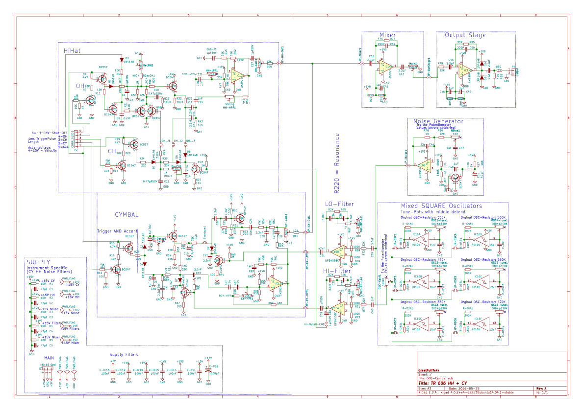
Phatline replied to Phatline's topic in Miscellaneous
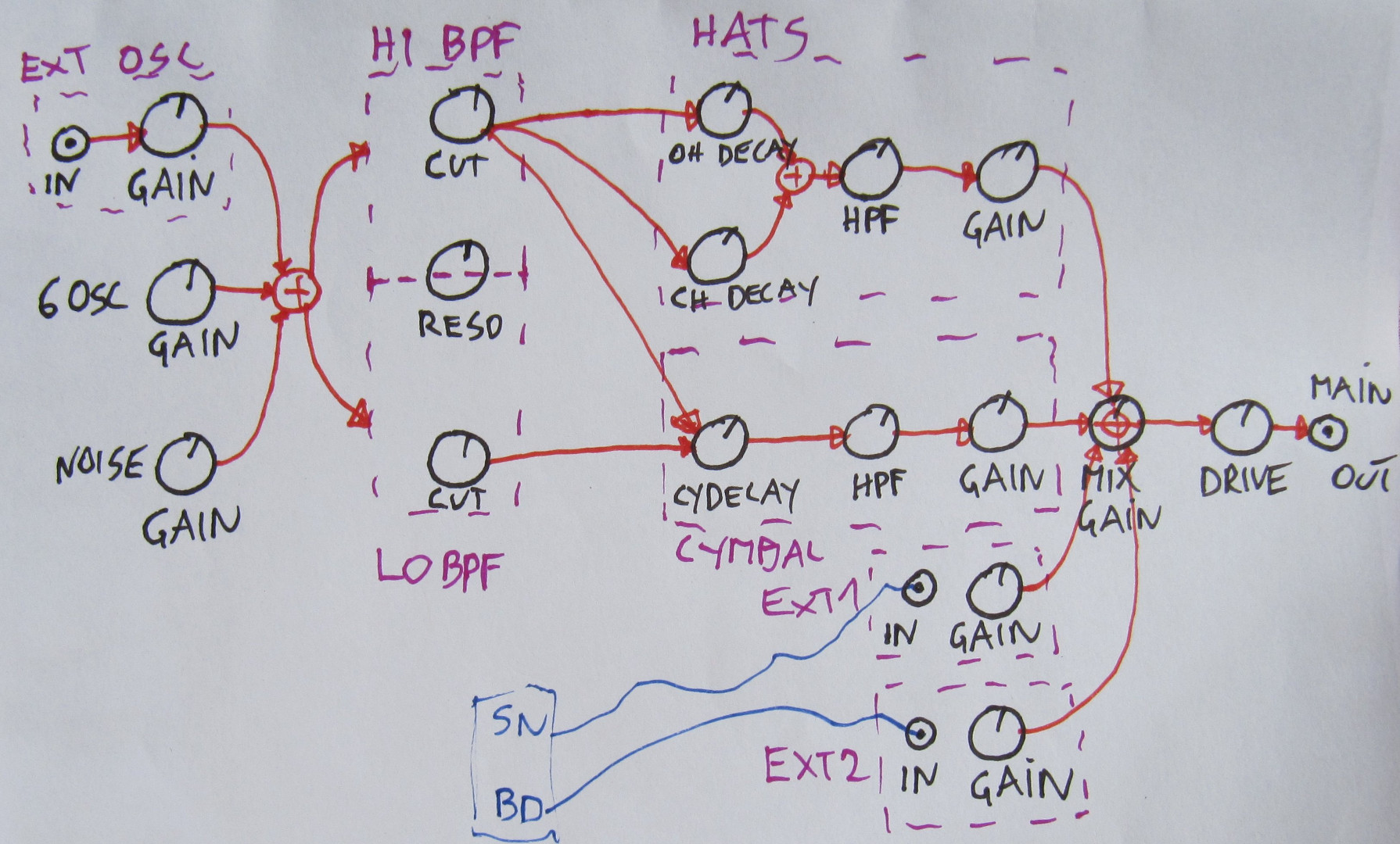
update: + noise source which is originally for the Snare Drum - is now mixable to CY and Hats + mixer section - so HH + CY-Mixdown should sound like 606... (filters? Impedance) +part of the original Power Supply Section which give every instrument its very own power source (left downer corner) - i don’t know exactly why they did this... +the 6Square Wave OSCs for the Metal sound: now are tunable with trim pots - in order to tune it to my Setup (A@~432Hz..) (by the way: 6OSCs? 606 interesting...) +added some explanation to the schematics - which i got from thru the internet research... +Add Jumpers for every Output from the different stages - in order to better debug the prototype - and to better mod - and to better tune - and to better make a modular... +pcb will be bigger then excepted - i lost the orginally Part Nrs as a mistake... i only restored the OP-Amps and Transistors - (bad) 606-Cymbal.pdf 606-Cymbal.zip
-
TR606 CY+HH Kicad Shematic (Capacitor labeling on old shematics)
Phatline replied to Phatline's topic in Miscellaneous
thx i put there a 2M now. i dont found backgroundimage settings... but a good idea to look at the orginal pcb. -
TR606 CY+HH Kicad Shematic (Capacitor labeling on old shematics)
Phatline replied to Phatline's topic in Miscellaneous
Shematic are all over the net: http://privat.bahnhof.se/wb447909/dinsync/service_manuals/TR-606.pdf Module: CY + HH on one Modular Module (Gnd, +15V), driven with a MidiBox Core32 - the midibox side is already programmed and tested a lot... there is somewhere a Topic on this.... Why only CY+HH.... whell, i have already a TR606 but i only use the Cymbal - and for that it is to big, so why then HiHats also? because they use the same Metall-Oscillators... but maybe i skip the HHs (they take much place) the midibox side i made 2015 here: but sorry shematic are very tiny because of Forum Move and Dead Gallery Pictures.... -
TR606 CY+HH Kicad Shematic (Capacitor labeling on old shematics)
Phatline replied to Phatline's topic in Miscellaneous
@Zam thx! i drawed the Cymbal and HiHat Section of the TR606 into Kicad Shematic... the pcb is still left, i dont have the mood right now... but maybe it helps anyone - anyhow... I have used the orginal NRs (R178...) and the MODs for this Section are in it... 606-Cymbal.pdf 606-Cymbal.zip it would help if KiCad whould place the components like or simular like on the shematic... > säcke.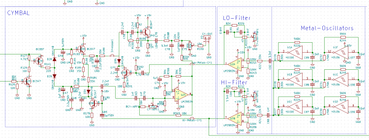
-
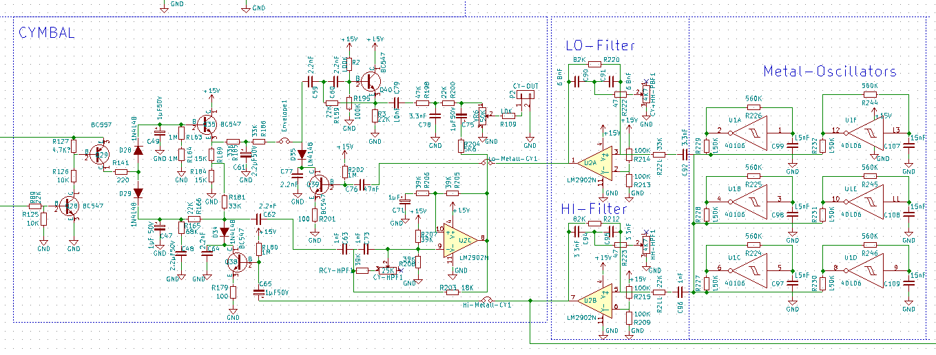
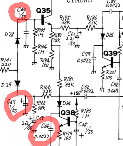
in the picture below - i marked 3 capacitors... i dont understand what that mean: C49 - 1/50 ---- i think that mean: 1µF 50V ... but 1µF is untypically for a unipolar Cap? C47 - 1/50 ---- 1µF 50V Electrolyt cap - could be C64 - 0.0022 .... ceramic 0.0022F? = 2200µF cant be > way to much for a ce rco... (by the way its the Cymbal circuit of the 606)
-
...this time only one cam...
-
thx, we will cam more of our weekly jams.... except the beer parts