stryd_one
-
Posts
8,840 -
Joined
-
Last visited
-
Days Won
1
Content Type
Profiles
Forums
Blogs
Gallery
Everything posted by stryd_one
-
Err whad ya grab that freaky LCD for? :-\ I assume you connected it to the 12V ground, not -12V? That 12V supply is really meant to stay nice and clean for the audio output anyway... But aside from that, I wouldn't have thought that the LCD should draw that much juice. if you put your meter in series with it, how much current is the backlight drawing? Seeing as it's just that backlight, it shouldn't be enough to overheat the 7812, so maybe there's a short somewhere, or the backlight is dead... I dunno. How much current does it draw if you disconnect everything from the LCD and just connect the backlight? Same as the above? Oh - how are you splitting up the 12V to the LCD and OPL board? in series or parallel (a spot of ascii art might help here)
-
Gday Jay welcome aboard. This usually indicates the core has rebooted. This could be a brownout error, or any number of soldering problems, or a problem with the PIC... First, I'd like you to read the link in my signature... We need more information, and you need to read around a bit more so that you find all the troubleshooting guides, tests, and such. You're uploading MIOS so I'll assume youve burned the PIC yourself (if you bought it from smash, it'd have mios on it already). I assume it's a PIC18F4620 because that's the file you're uploading to it. I'll assume you built the PCB yourself because you didn't get the PIC from smash, I'll assume you etched it from the v3 layout on ucapps.de, I'll assume you already did the voltage tests before you inserted the PIC and after as per the ucapps page, I'll asssume you tried the midi troubleshooting guide and it all passed... Uhm... Maybe I'm assuming too much. Maybe you could tell us ;) While you're at it why don't you mention the midi interface you're using (you can check the wiki and see if it's one we already know has problems) and whether you used Smart Mode and Wait for Upload Request in MIOS Studio, and it's the latest version (7b5).. And anything else you can think of :) Don't be shy with the details, it makes it a lot easier and faster!
-
DIY audio patchbay with digital routing....How hard?
stryd_one replied to Nomical's topic in Design Concepts
LOL. Yeh and a whoooole bunch of design concerns that would leave me totally out in the dark... I'm sure you could use IC's with multiple transistors and make the job easier but yeh.... Unless you know how to do it, I think that one might go in the too-hard basket ;) Yeh I always thought It would act like a big antenna but I don't know sh*t from chocolate on this stuff ;) Anyway it's all in that PDF, I'll leave it to the pro's at AD to explain it before I start looking (more) stupid heheh Totally! I bugged out on him in the chat room, I guess my enthusiasm would have shown a lot more at that time :) In fact I think I blew him a smiley kiss (that's like a double disgust for poor bugfight too) after lots of yelling and excitement. Yeh I can see how it would seem that way, but that's not the intention at all - it's not so much that we are ignoring his work, not at all, in fact I believe that final credit in our device should be shared with him because he has been kind enough to furnish us with some healthy advice, and schems for things we did not have like the buffers and PSU too. Although tilt is re-doing them, I'm sure that he (like me) will be referring to them as a guide. But as you can see from the thread, the design we have now is one that has evolved through a discussion aimed at meeting everyone's specification, so it was heading in a certain direction as a result.... By the time we knew enough about the docmatrix, it already had momentum, and we're just following that momentum. Myself, not speaking for anyone else, I would prefer to use the AD chips, so I probably would have kept along this path even if I had known of the docmatrix, but if someone else would be happy with doc's design then I think they should build it, cause it's excellent!! It's like...when I heard a really cool tune that MTE sent me the other day, I didn't stop making my hiphop track because his trance song was so cool... I thought it was great, but I was doing my own thing... but that's no disrespect to MTE's tune :) -
I believe that someone has been working on a schematic for using the MBSID Optimised PSU with the MBFM but it might be a little while before they can talk about it... But it has been described before. You do need to add some circuitry to make it work.
-
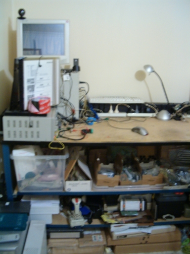
Yeh comon guys post your pics! Don't be unhappy with your setup - I guarantee no matter what it is, someone has one better worse than yours... or just different. We thought it'd be cool to have a "show us your lab" thread, and everyone's gone scaredy-cat! Don't be shy :)
-
Yeh TK's probably on the money there (no surprise!) :D Something else you could check, is the traces between the midi I/O and opto/core - a short in the right place will make it go a bit pear shaped... Yeh man that's what I thought too.... but a couple months back in the chat I spent about 2 hours troubleshooting because I made that assumption, turned out there was a short under the opto that wasn't seen because I told the guy that test wasn't needed . oops! The test isn't meant to check for such things, but this was a lucky break ;) He had a couple of loose pins in the opto socket and had spilled solder on there while fixing it up. Sometimes it's better to do the test and "know" for sure. Regardless, that's just theory now because TK is gonna be right... we seem to be seeing a few of these lately. If you're using a USB midi interface from a hub, as an alternative you might like to try it direct from the port on the PC, or with a powered hub if you have one. But I think that trick only helped with one person, the others had to do the mod TK suggested. Good luck!
-
DIY audio patchbay with digital routing....How hard?
stryd_one replied to Nomical's topic in Design Concepts
Exactly. It's just like a 595 :) The tricky part about the layout is the grounding - I'm no guru on this as we know but I do know that you want to keep analog ground wires and traces physically inbetween the analog signals, and digital ground should be separated, and you want a big analog ground plane... As well as avoiding sharp corners on the traces etc. I think you were around in the chat when we discussed that? I highly recommend reading the AD8113 datasheet for the lowdown on all this, there's a whole section dedicated to it with several pages of "Do's and Don'ts ". As for the CS stuff maybe it would make sense for me to use the 4685 so we have the option of using MBnet. Doc has clearly demonstrated that an external CS is possible without it though ;) But some other more processing intensive CS suggestions have been made whech would probably need a separate core. I agree. Fortunately as tilt has said the interfacing to the chips is a bit of a walk in the park really, and it won't be the first time I've written a driver for something like this, so the real problems are not so big... but I don't want to get too distracted with the CS. Supporting a basic 2-encoder+LCD interface and a LED matrix should be fairly straightforward, and I'm cool with refining the details a bit, but I don't want to get too deep into it just yet. Gotta keep focussed :) Edit just for your info - the very first working build of this will likely be a CS-less core with CC's to select the IO and a note to engage it. After that I'll put sysex and encoders/buttons in place for the same, then the LED matrix. Roger - out of interest, how big do you want your LED matrix? -
Why are you connecting the LCD to the 7812?
-
DIY audio patchbay with digital routing....How hard?
stryd_one replied to Nomical's topic in Design Concepts
No sweat bud, it's supposed to scale up AND down :) Tell us what you need, I'm sure it can be done. I'm really keen that noone be left out on this (unless they want something wayyyy different, which I haven't thought of yet), and besides, the practical difference between a big 128X128 array with encoders and LCD and a remote led array, and a simple 16x16 with no CS controlled by midi and built into a synth, is not so big :) Rad, I have a couple tubes of them :) I must admit I did think about strapping one to the back of each of my 8 channel vale pre's... Heh :-[ -
Welcome aboard! :) Please read the link in my signature - it is very important to COPY and PASTE your logs. For example, one time someone said that they did the loopback test and they recieved the same sysex that they sent. In fact, they recieved a different sysex and didn't notice it. It's good to have a fresh pair of eyes double-check these things. Please do ALL of the tests and post results from each.... We'll see how we go when we have all the info :)
-
DIY audio patchbay with digital routing....How hard?
stryd_one replied to Nomical's topic in Design Concepts
Keep the ideas coming guys... Perhaps you could think of a good way to make the LED matrix scalable, IE 'pages' of LEDs, we'd need up/down/left/right buttons, and some way of showing where we are now, or something... You guys have better ideas than me on this LED thing so I'll see what you say :) -
Although I think you may be right, that might not be the best way to find out. At this point, you should really disconnect all the peripheral boards (like the OPL3 module) and just work on the core. The 7812 should have nothing to do with the core at all, it's only for the audio circuitry on the OPL3 board, so I don't understand why the LCD would effect it. I suspect you have a short circuit somewhere. Trying another set of FM chips might help, it might also blow them up as well. Fix the core first. (see my signature - one at a time)
-
DIY audio patchbay with digital routing....How hard?
stryd_one replied to Nomical's topic in Design Concepts
Awesome, thanks tilt! I better get started on the software huh! Should I grab some of the chips now, or are we a little while off? No rush! :) Plan I'm thinking of at the moment is to buy 2 chips for you, and 4 for me, and one each for a few other ppl, so that we can test it (and you and I can test chaining). Meantime, I'll get the UI happening and just send the data via sysex or something to make sure it's being saved right... That might take a couple weeks with my current spare time.. Then it should be a matter of strapping in the driver... illy: Totally agreed. Perhaps they made the same mistake we did, in their pre-production ;) Bunsen: I'll work (later) on a led-matrix option with optional scroll buttons, but don't think the GLCD thing will be part of the standard build, at least, in the initial releases. -
Errrr.... that's not an 808. ??? TShirts.... Posters.... Must be getting "trendy". This video is no longer available due to a copyright claim by NBC Universal Oh yep. "Hey that's worth money now that it's "trendy", give it back!"
-
the 7812 should only be powering the audio circuits which should draw...next to nothing. There's definitely a short there. Maybe inside a busted OPL, but that's not right. How?
-
is it just me, or is the FORUM going OFFLINE alot ?
stryd_one replied to Artesia's topic in Miscellaneous
IRC bad. Patience good. -
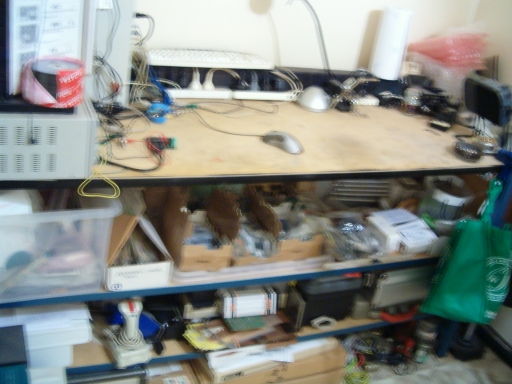
It's a workbench not a desk, you stand up at it :) Thanks BF! Aussies: Go here http://www.techtron.net.au/xcart/product.php?productid=18513&cat=0&page=1
-
10 points for originality :)
-
Oh I forgot, the most important part of any lab, the bug! This is the uncle of the one that's currently hanging out here, but he's camouflaged, and asleep so I don't wanna shoot flash photos. They come by all the time. The one in this pic is about 3" across... Yes, he really is winking at me :D

-
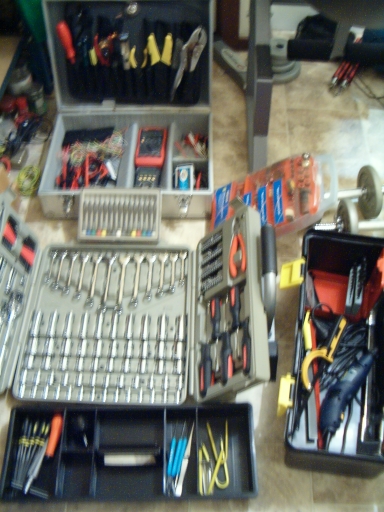
I love that mega big soldering clamp thingy!! You gotta link for that by chance? How's that chief? ;D All components in labelled smashtv boxes, pricey and delicate stuff (tubes of filters and sids and delays, GSSL and wilbasid kits etc) in the big white bin of pleasure, tools including USB scope and various meters (cheap ones are sacrificial lambs) and dremel all stowed, drill press out of the way underneath the green bag full of safety gear...where is your safety gear? Oh, you must have been wearing it when you took the pic huh....yeh right ;) Note the coffee jar next to the soldering iron stand, that's for holding 0.001% tolerance cut resister leads. Actually it's hard to spot. Back-right corner of the desk, that's a hakko 936 ESD clone next to it. I need a new camera.


-
Yes! :) AUAIMBCTG! (Search for it ;) ) Sure does! I had a b*tch of a time finding it last time, and so I put lots of keywords in one of my posts on this thread: http://www.midibox.org/forum/index.php/topic,9668.msg70349.html#msg70349 That has all you need to know :) Actually ,I found that when I searched for 'star wiring pots'. What'd you search for this time? We should add the words to the posts here so it'll show up for the next guy's search.
-
DIY audio patchbay with digital routing....How hard?
stryd_one replied to Nomical's topic in Design Concepts
Heh I think I said the same in the chat the other night.... You could make the other encoder pushbutton too, for preset selection. Only worry there is unintentional patching. Maybe an "are you sure" type prompt would be good, then you can just double-click to confirm instantly, if youre really sure ;) Hmm you really need to store the position of all the switches I think... Although you could maybe just store the On switches, and clear the matrix when loading a preset... I think that storing all positions will be easier to handle. Given that memory is not a concern... Well, the way it's arranged is per-chip. 16 bits are used to store the switch states for each row (Y pins on the chip). Each bit represents the state of the switch to the columns (X pins) There are 16 sets of these for each chip. It counts from the last Y pin (y15) and last X pin (x15), then second last X pin (x14), third last (x13)... until it gets to the first X pin (x0), then it starts again on the second last Y pin (y14) to x15, x14, x13...x0......etc..... If there are multiple chips, it starts at the last chip and works it's way up. This means we'd have 256 bits per chip. Obviously we would tell the app how many chips we are running, so it knows to read 256* that many chips from the bankstick. Sidenote: looking at the timings, there are no maximums for loading the individual bits into the IC, so we probably won't even have to buffer it, just read direct from the bankstick to the chip (OK, it makes sense to use pageread to grab big chunks from the bankstick, but anyway, no need to buffer the whole thing). The only maximum is for the PCLK strobe (which tells the IC "I'm done sending you data, now load it into the switches") which has a 5ms max - plenty. The minimums are actualy kinda long, I can see us needing a few NOPs in the driver ;) Essentially it goes: Set the SIN (data input) pin according to the switch position. Hold 20ns min. Set SCLK (serial clock) pin high. Hold 100ns or more. Set SCLK (serial clock) pin low. Hold 100ns or more. Rinse. Repeat. Allow max 5ms wait here, no more! Set PCLK (Parallel Clock) pin low. Hold 65ns or more. Minimum SCLK speed is 20khz, no problems there, might be smart to disable interrupts while it's loading though. If we only stored the switches set On, then we'd have to calculate all these bits before sending to the matrix. That's not too hard, don't get me wrong, but it is kinda indirect. Also, storing all the bits makes it easy to look up the switch's state - you just jump to the appropriate bit, and see how it's set. If we only store the connected pins, then we would have to read them all, to check. Again that's not hard, and wouldn't take long especially if there weren't many connections, but it is indirect. LOL well that's the thing - the PSU and buffers are total voodoo magic to me. The other stuff is easy :) (especially as stromeko was kind enough to publish his eagle schems for the matrix! No buffers there though) PSU's shouldn't be too rough, there are plenty of designs around to plagiarise take inspiration from... Probably the same with the buffers if I search some DIY sites.... But both of these have all these extra components; using the buffers as an example it's not just the opamp there are resistors and caps and I am stuffed if I know what values we need. Yes that would be way handy. We could probably just get the app to mirror configurations with neighbouring pins... so if you patch source X to dest Y, it also patches source X+1 to dest Y+1... Sound right? You'd need to connect your stereo pairs physically to neighbouring pins, but I imagine everyone already does that anyway... Warning - while you were typing 3 new replies have been posted. You may wish to review your post. Damn, this thread is on fire! Ahhhh, my bad! Heh, you just happened to be playing with the idea as it was being discussed here - synchronicity! :D Yeh I was talking to DrB about the "join the team" stuff :) When I said "That looks like the docmatrix way of doing things." I just meant the CS :) Although I would be lying if I didn't say that I was disappointed that I had been trying to drive this concept for years, only to find that while I was pushing it, it had happened with me excluded*. But... It's your project! And that is cool with me :) *PS just to be clear I don't feel I was deliberately excluded, just maybe forgotten - I don't think you did anything mean, or anything like that! There are no complaints from me about docmatrix or especially my buddy doc! :) It's not quite that simple in software.... Heh, thanks man!! I didn't want to mention these just in case it was a secret ;) Now you know why I didn't mention your name when I said Warning - while you were typing a new reply has been posted. You may wish to review your post. We don't need no water let the mother ****er burn.... OMG you got that right!!! -
DIY audio patchbay with digital routing....How hard?
stryd_one replied to Nomical's topic in Design Concepts
Ahh interesting point... I was thinking about it from a " 'This' goes to 'there' and 'there' " kinda perspective, but hadn't considered that. As you noticed, the 75019 and 8816 can do many-to-one connections, although it's not really advisable. I'm sure you could overload the destination device's inputs doing that, if not the output buffers, if not the matrix itself. Not sure what damage it would do but I don't want to try it and find out ;) Anyone know? Ahh sweet. Yeh those are nice (why can't I find pricing? I'm having a bad time with Google's now algorithms. Anyone use a different search engine?). I notice the screen on those has the source on the top line too... I was thinking it shouldn't be hard to have the software prevent many-to-one connections. You could just read the crosspoint's status from other sources before setting it (by jumping X bits through the patch where X is the number of input channels (well actually it's not stored like that but that's an easy example)), and pop up a message to the user with the names looked up like: Delay2_1 conx to s2k_6 overwrite or mix? and then they could select using knobs and buttons, and you could disable the mix function in software. But.... is that worth doing? I think a "destination from source" method like you suggested, would make sense as much as a "source to destination" like I spoke of in my last post, if not more. In fact, if the software was restricted to having one source per destination, that could also make the memory usage easier, because you could just have an array of unsigned chars with the number of elements set to the number of destinations: destination[32] destination[cs_dest_sel] = cs_source_sel Makes it look a bit easier! heheh Another UI idea I had was an 'insert' function... Say you have 's2k_6' routed to 'mix_ch28'. You want a delay on that sampler. You select your destination 'mix_ch28', which is already patched to source 's2k_6'. You select the new source, 'Delay2_1', and by using a key combo (hold down preset button while hitting On/Off?) you are prompted for another destination. You select 'Delay2_1' (same label, but remember one's an input and another's an output) and it not only redirects the mixer to receive from the delay, but also redirects the delay's input selected in the prompt, to receive from the sampler. Only trouble I can think of, is that it would need to ensure that the delay's input was not connected to some other source already. If it was, it could fail, or maybe even prompt for an alternate patching somehow. Also, this could be used as in my first example, so you would be prompted "Overwrite,(mix, )or insert?" OK seeing as I'm thinking about use-cases... Source and Destination makes sense from the matrix perspective, but in the real world we'll be patching "output" to "input" not "source" to "destination". Maybe we could have a #define that the user can edit, so that they can change it as they see fit. I'd rather my screen say something like : To 'mix_ch28' Input From 's2k_6' Output than Dest 'mix_ch28' Src 's2k_6' Just because those are the words I would use in real life. Anyway such things are probably too fine a detail at this point... We need someone to start on a layout so we can order prototypes and start writing in C instead of english :) If there's anyone who wants to volunteer please shout out now... We'll love you forever and be your best friend! heheheh If someone doesn't put their hand up soon, I'll do it, but lord knows how long it will take me.... My projects are kinda glacial; they are large and they move slowly (primarily because they are large and so they cost too damned much). nILS said he could make a layout if we have a schem (THANKYOU NILLY!) and he's away for a bit, so I'll have a couple weeks to get a schem made up...but I'll almost certainly need help, especially with the buffers/balancing I/O, PSU, etc.. I have some very good starting points (THANKS!) but... I'm a fricken total n00b :) More ideas in the meantime? Warning - while you were typing a new reply has been posted. You may wish to review your post. Yeh, join the team man, don't be a solo player and leave us in the lurch :) This has been the primary factor in the failure of this project to take off in the past - one person who could be really helpful, takes the idea and runs with it (buying chips before the group decides on one, making CS layouts without talking with the group). In the end, the individual's project may or may not be finished, but it's not what the whole group needs, and the group project may die because people lose interest. Action is definitely good, it's no good to sit around and talk but never "do" - but I hope you'll "do" with us, not "ahead of us" :) That looks like the docmatrix way of doing things. The LEDmatrix definitely gets top marks for bling factor, and it should be easy to fill it from the stored patches. Course, it won't grow with different setups.. I definitely think that a LED matrix of some sort would be good as an option though. Also you probably want more than 4 chars per name, because you'll want numbering in there, which leaves you with only 2 maybe 3 letters to ID your kit. I do like the idea of having a quick overview of where things go though. Again would be handy in the "where the **** is that synth coming from" scenario ;) Warning - while you were typing 2 new replies have been posted. You may wish to review your post. Hhehehhehe I think you're coming up with too many options which won't scale up and down very well... could make things difficult from a coding perspective because the app would need to have all these different options built in.. That said, I think it's good to consider possibilities so that it will be easier for people to implement custom CS - but I think that the default (IE, ready made) CS should be a lot simpler and more scalable. -
CLOSED: Black Re'an P401 Soft-touch knobs - 39 cents each
stryd_one replied to nebula's topic in Bulk Orders
Maybe you're right... I paid a long time ago :) -
DIY audio patchbay with digital routing....How hard?
stryd_one replied to Nomical's topic in Design Concepts
That's three of us... Any objections anyone? Don't be shy! If you send two sources to one dest, the result will be double, so you'll need to turn down the source. If it were a summing mixer, the destination would be halved automatically to compensate. I think it's linear not exponential but the figures ain't pretty... If we have a consensus on the chip, yep. Yeh it works well with midi... Bankstick won't be an issue, we got at least 64k per chip and only need one bit per crosspoint. We can have 8 chips. No sweat there :) Dunno about 2x24 cause it's an unusual resolution, 2x40 would work just as well though. Problem with the above example is that it doesn't allow for connections split amongst more than one group of eight. Also, it should be pretty easy to be able to name the connections, which would be *really* handy, especially for big routers and for modular synth patchbays. My idea so far had been very minimal, just a source and destination - 1 knob for each, On/Off switch, and edit/preset switch. On the LCD, where the source is selected with the first knob, the first row will show it's name, 2nd row shows the destination just using a 'block' when it's On. You select a destination using the second knob (which makes the corresponding 'block' character flash, and the name appear on the top row of the LCD) and hit on/off to engage/disengage it. Shouldn't be difficult to make it work the other way either, so you can select a destination and it will show you which sources are routed to it. ("where the *** is that synth coming from" will be areal problem when you can't follow a cable ;) ) This could be done with 7-seg for the source/dest numbers, so it's easily visible. It also means that any LCD should be big enough because you scroll the bottom row left and right when you select the destination. So long as there's enough room on the top row for the preset number and the port names. Names storage shouldn't be an issue either - even for 128x128, if you allow 8 characters per label, that's 2kB. Barely a scratch on a bankstick. Sounds good. Nah... You just have groups of bits to send to the switches and pointers to those for each preset. I hope it comes to fruition this time! The software part of it is really pretty straightforward. It's memory hungry but the banksticks have thah covered, but otherwise it's a snap. The trick, at least for me, is the analogue stuff..... That's where I need help.