Wilba
-
Posts
3,310 -
Joined
-
Last visited
-
Days Won
2
Content Type
Profiles
Forums
Blogs
Gallery
Everything posted by Wilba
-
I think most bridge rectifiers have voltage/current ratings far higher than what you'll ever use for a MIDIbox. You should be OK using anything you can salvage from a C64, as it handles 9V AC 1A input. Just pay close attention to the pinout, as incorrect wiring might result in a diode "shorting" your input power.
-
Matching switches to protoboard/veroboard holes
Wilba replied to findbuddha's topic in Parts Questions
I may have bought some before like the first link... I recall it was a pack of 5 with similar dimensions. I wouldn't worry about breakage in transit, the phenolic stuff is actually pretty flexible, and even if packed flat in an envelope it will survive postage. Photo shows some stuff I got ages ago, either from Dick Smith Electronics or maybe Futurlec (ugh!) probably from the last order I ever did with them, highly unrecommended. You're right though... most local places have stripboard or nothing. Try Altronics or Rockby perhaps. -
Matching switches to protoboard/veroboard holes
Wilba replied to findbuddha's topic in Parts Questions
I'm surprised it doesn't fit... this switch is the one I use a lot (MB-SEQ, sammichSID) and it seems to fit my prototyping PCBs nicely. You probably don't even need a drill bit, just using the tip of a craft knife should be enough to widen the hole just enough for the pin. -
Why would I be offended? :rolleyes:
-
OMGWTFXKCD!
-
Since those headers are expensive, hard to cut without splitting them lengthwise, and more than you need for one sammichSID, I chop them up into 2x8 and 2x5 headers. The downside is if you want to replace your LCD, you need another header, so it's sort of easier/cheaper for me to send out replacement headers as required than force everyone to pay for more than half a 36x2 pin header that they're not likely to use.
-
LMAO I think we should link to this whenever someone posts "can I have circuit diagram 4 this"
-
I use mouser part 517-836-04-36 but I can just add a spare header to your kit.
-
sammichSID E-Switch does not work **FIXED**
Wilba replied to neosay's topic in Testing/Troubleshooting
Good to hear you got it fixed! UG GLUG GLUG :wacko: -
MIDIbox of the Week (MIDIbox CV of Altitude)
Wilba replied to Altitude's topic in MIDIbox of the Week
Thanks Alt... regarding asking how you did white, I was getting confused, as I'd checked out the transparent stuff before. I might try the laser printer stuff since I inherited a big colour laser printer. -
sammichSID E-Switch does not work **FIXED**
Wilba replied to neosay's topic in Testing/Troubleshooting
You're right, I meant pin 12. If shorting pin 12 to pin 8 doesn't work, then it's not the switch. Please explain what you mean by "or the value is flipping to a very high or low value"... do you mean the value of the parameter? What is the voltage of pin 12 when the switch is unpressed? It should be 5V. Maybe resoldering pin 12, and the adjacent pin of the resistor network, could fix something. Just a guess. Also you should check if the resistor networks are correctly oriented with the dot in the label aligned with the dot on the PCB. As I just recently explained in another thread, the LABELS of all the resistor networks should all face the same way, towards the top of the PCB. -
MIDIbox of the Week (MIDIbox CV of Altitude)
Wilba replied to Altitude's topic in MIDIbox of the Week
Great job, Alt! I'd like to know more about the inkjet printable vinyl... how you achieved white on black etc. Maybe a brand or source would be cool too. I want to try something like this on some Cherry MX keyswitch caps, only on the side of the key where it won't wear off, though maybe a second layer of clear vinyl might let me put it on the top too. -
sammichSID E-Switch does not work **FIXED**
Wilba replied to neosay's topic in Testing/Troubleshooting
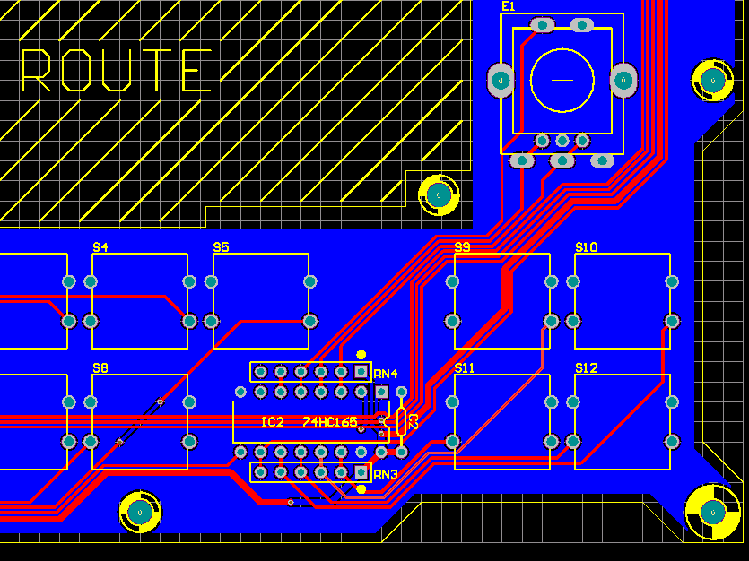
Check if it's the switch at fault, or the connections. This is easiest done by shorting across the two left pins of the switch while the sammichSID is on, and watching for an effect. You can also test if "grounding" IC2 pin 11 works (i.e. what that switch connects to - follow the track in the attached picture). You can connect pin 11 to pin 8 (ground) with a wire or even the tips of long nose pliers. Be careful not to short any other pins while you do this. Depending on the results, you can then work out if the switch is not closing, or there's a break in the track somewhere (i.e. even shorting the pins of S12 doesn't do anything). If the switch is the problem, I'll send you a new one, but it would make sense to check it's definitely the switch at fault.
-
:frantics:
-
Topic split... new bulk order thread formed
-
sammich - one of the sidchips is not making the sound **FIXED**
Wilba replied to legolars's topic in Testing/Troubleshooting
Cool... I assume I can mark this thread as **FIXED** now :D -
I will run another OPL3 chipset bulk-order, but to save me time and effort, grizz will do the collecting of names, and I will do the collecting of PayPal payments and posting of orders. If you want brand-new YMF262 and YAC512 for your MIDIbox FM project, this is the best way to get them. Estimate price is 12.75 AUD per chipset + 2.50 AUD shipping worldwide (up to 10 chipsets, more probably, they weigh almost nothing).
-
SammichSID - problems with voltage tests **FIXED**
Wilba replied to unikoi's topic in Testing/Troubleshooting
Good to hear it's all fixed now! -
I've been waiting all weekend to be proved right. So RN3 and RN4 are positioned incorrectly. I have no idea how your encoder is working with RN4 the wrong way around! Since all the RN parts are aligned the same way, i.e. horizontally with common pin on the right side end, all the •6A103G labels SHOULD BE facing upwards, towards the display. Sure, no problem. Please advise me how you would change the build guide to prevent others from making the same mistake :tongue:
-
I just realised I added up incorrectly in my explanation... I didn't add the 0.5mm offset. Basically from the edge of your PCB, add 0.5mm clearance, then another 0.1mm for laser burn. That's the start point of the "teeth". For the end point, from the edge of the PCB, add the 0.5mm clearance, then 3mm (panel thickness) then another 0.1mm for laser burn. I can't really say what's best for an interlocked panel when there's nothing else holding it. From experience, the LCD window on sammichSID is cut to be the same size as the panel cutout... i.e. given a size you want, add 0.1mm offset all around for the inner part (clear acrylic) and subtract 0.1mm offset from the outer part (panel cutout). Then both parts will be the same dimension and "snap fit" together. You should use rounded corners to make it easier to put in, and prevent cracking, and also apply the offsets to the corner radii. So... you could do the same... offset the "teeth" edges on both parts by 0.1mm outward (i.e. make the teeth wider by 0.2mm thus also making the gaps narrower by 0.2mm). This makes both parts identical after cutting, and it should "snap in" without needing nodes etc. If you want to be fancy about it, you could make nodes of 0.1mm instead of widening the entire "tooth".
-
sammich - one of the sidchips is not making the sound **FIXED**
Wilba replied to legolars's topic in Testing/Troubleshooting
Is it 12.26V straight out of the power supply or was that measured on the PCB (i.e. at a pin marked "12V")? Did you measure this while the LCD was connected? If it's connected, this will draw current and affect the voltage. I can't find an order for your MIDIbox username, so I don't know if you're using a high-power or low-power LCD. Setting to 9V might not work, if you had measured 12.26V going into the 9V regulator, then setting the power supply to 9V might drop it by 3V and it won't be enough for the 9V regulator, which needs 10.5V or more to operate. You don't need 12V for 6582A... but you need enough for the 9V regulator. Also, high-power LCD backlights are powered by the input voltage, before going into the 9V regulator. The issue is, unregulated power supplies should deliver their rated voltage when the current load is at the rated current. When the current load is smaller, the output voltage will be higher. So it's probably a good idea to find a power supply with a smaller maximum current (perhaps 500mA). However, I've run my sammichSID with a regulated 12V power supply, and I don't think the PCB gets too hot, it's definitely hot, but I've noted that the regulators are dissipating well... if they were getting too hot, then the ends of the heatsink fins would also be getting too hot, which they aren't. -
I'm not sure I fully understand the question. I started with the PCB size and added clearances and thickness of side panels to make the final outer size of the top panel. i.e. if the PCB was 100x100mm then the "start" of the teeth are 0.5mm offset from this, then the "end" of the teeth another 3mm offset. Then ALSO I shifted those offsets by 0.1mm outward to allow for laser burn. So the design would show final outer dimensions of 100+(2*3.1)=106.2mm I didn't include "bumps" (nodes) on the teeth or added offsets to allow for laser burn, as the idea is not to make it a tight fit. Thus there are 0.2mm gaps between the teeth when they interlock. It is the top panel screws which apply pressure on the sides and hold it together. To achieve this, an extra 0.5mm gap is added between the top spacer and the top panel... i.e. the dimension between the "start" of the vertical teeth on the side panels should be the sum of the spacer/PCB/nut heights plus 0.5mm so that when the top panel is screwed down, the clamping effect happens on the sides and not against the top spacer.
-
sammich - one of the sidchips is not making the sound **FIXED**
Wilba replied to legolars's topic in Testing/Troubleshooting
Maybe your power supply is too high rating... i.e. 12V AC 500mA is good, but 12V AC 1A may supply input to 7809 with a lot more than 12V DC. Check voltage of pins marked with 12V on the voltage test diagram. The heatsink is supposed to get hot, but it gets hotter if more voltage is supplied to the regulators, more than the regulators need. Exactly where do you say the "PCB" gets hot? -
Can you check if RN3 is oriented correctly? (also check RN1, RN2 and RN4). From this photo, I cannot see the label on RN3, which I expect to see on the side facing the IC. It is leaning away from the IC, and from that angle I can't see any label. The label should be •6A103G where • should be aligned with the white dot on the PCB. Therefore, the label will be facing AWAY FROM the IC for RN2 and RN4, and facing TOWARDS the IC for RN1 and RN3. This might explain the button problems... if RN3 is not placed correctly, then all the input pins will have a variable pull-up to 5V... if one switch closes, the other inputs drop from 5V to 2.5V... lots of weird stuff happens, I won't bother with more explanation, but it would explain the multiple problems you have, and that one switch seems to be registered as other switch presses. Resistor networks are a real pain to remove, like IC sockets. If it is incorrectly placed, I would recommend you cut it and remove each pin separately, and let me send you a replacement resistor network.
-
Check if the bottom-right pin of S10 is shorting with (connected to) bottom left pin of S11. I can't see how this could happen even with bad soldering but that's the effect.