

Wilba
-
Posts
3,310 -
Joined
-
Last visited
-
Days Won
2
Content Type
Profiles
Forums
Blogs
Gallery
Everything posted by Wilba
-
It's definitely not 1 gigaohm... more like 47 ohm which is way too low. Why are you using resistors which you don't know the value, and which are much lower resistance than those specified in the parts list (220 ohm)? In the build guide, I suggest using a higher resistance for brighter LEDs, and testing the LEDs with resistors first (if you're not using known resistors like SmashTV's red LEDs). I recommend removing the resistors and replacing with 1K resistors, or at the very least, 220 ohm resistors. After you desolder the resistors, you can run the LED matrix test app and test which resistor value you prefer (1K or 220 ohm) by touching them on the pads... only some LEDs will light, but you can judge from that if it's too dull or too bright.
-
Cool... good to hear you solved it!
-
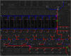
Since there are several capacitors between 5V and ground on the PCB, testing resistance between 5V and ground tracks sometimes causes unexpected results, as the capacitors get charged by the current coming out of the multimeter. On my multimeter, there's a "continuity tester" mode - it beeps if theres a very low resistance between the probes. Sometimes testing between 5V and ground will beep for less than a second, as the capacitor is being charged by the multimeter, which senses this as high conductance. Once the capacitor is charged, the beep stops. Perhaps what you are observing is the same thing. On your friend's one, testing resistance is showing a non-constant resistance because the capacitors are charging. On yours, the tracks are (we suspect) shorted, and so the capacitors are also shorted and don't get charged. Here's a picture where I think you should break tracks to discover which section of the 5V tracks are shorting to ground. Start with the locations marked with green circles. Then you can decide which of the other locations (marked with pink circles) you can use to narrow it down. This is only a suggestion... you want to cut tracks until you get it down to a few pads that must have the short, then you only need to desolder a few components and check if that fixes the problem. i.e. let's say it's one capacitor between the 5V/ground tracks that is shorting (the capacitor itself, not solder blobs) then you'll never find out which one just by looking at solder blobs. Similarly for all we know there's a short in the copper between a pad and the ground plane. Finding it will be very hard if you don't narrow it down to a smaller area to look and start removing components. I wish I could suggest an easier way but there really isn't, and I think you've given up on looking for solder blobs shorting... it probably is something else. Let me know what your results are after cutting tracks... draw on the same picture showing where you cut and which section is shorting.
-
Can you explain exactly what you mean? Do you have knobs that decrease values when turned clockwise?
-
Note that encoders work by "shorting" between the common pin (connected to ground) and the other two pins. Let's call A and B the pins connected to the input pins (i.e. the DIN module, or 74HC165). C is connected to ground. Thus as the encoder turns clockwise (for example), A and then A+B and then B are shorted to ground. If turned anticlockwise, it would be B, then A+B, then A. Hence you can tell which way the encoder is turning based on the pattern. http://en.wikipedia.org/wiki/Rotary_encoder So an encoder with all pins being connected isn't necessarily faulty if it happens to be at one of the positions where A and B are both connected to C. If it were always connected, it wouldn't work at all. I am a bit confused now... I can't see how a hardware fault can cause encoders to work backwards... I mean if the wires were swapped that would make sense, but this is a PCB with fixed connections between encoders and the shift registers. Shorts on the PCB would result in encoders either not working or maybe only working one way (increasing values regardless of turn direction). Could there be swapped wires between the CS PCB and the base PCB?
-
SidFilD - a SID filter/blackbox diagnostic tool
Wilba replied to ris8_allo_zen0's topic in MIDIbox Tools & MIOS Studio
Attachments got a bit mixed up during the forum change. I've fixed it now. -
The resonance knob should work like all the others... clockwise = increasing value. All the encoders should work the same way. Are you sure you used the same kind of encoder in all locations? Check for shorts with those pads, though a short would probably show up as the value always increasing or decreasing regardless of turn direction.
-
Maybe, the LEDs don't depend on working 74HC165 ICs, but they do share two common tracks, perhaps there was some interference. What kind of LEDs are you using? Ultrabright LEDs with low resistance resistors might result in some "ghosting"... LEDs being lit because that row was lit in the previous column of the LED matrix.
-
My apologies, your pre-order email was received but I forgot to add it into the spreadsheet and reply to your email. Based on the date of your email (15th Dec), you would have been placed into batch #9. However, I will fill an empty place in batch #7 with your order. Since you don't want SIDs, this will not affect the SID availability for people after you in the list. :thumbsup:
-
Are you still trying to perpetuate this myth, Razmo? :rolleyes: Now that you have a sammichSID, put your 8580R5 next to a 6582A and do some side-by-side samples using the same MONO patch. Then share the patch so I can hear the difference too with my SID collection. I tried really hard to get a different sound out of my MOS 8580R5, CSG 8580R5, CSG 6582 and CSG 6582A and can't. I stopped trying when I sent a dead 6582A to that guy who takes photos of the silicon die inside SIDs. He confirmed the 6582A die has the same "8580R5" markings. I'd really like to know how you get different sound out of them, and whether you have a "different" sounding 8580R5 or 6582A.
-
Guide to electronics connectors and wiring techniques?
Wilba replied to findbuddha's topic in Miscellaneous
this is useful: http://avishowtech.com/mbhp/crimp.html -
Surely I would email everyone if and when things don't go to plan... surely... :rolleyes:
-
Surely I put an estimate in the order confirmation email... surely... :rolleyes:
-
Don't buy one - I will get my German slave to post you a new Soundwell encoder. :thumbsup:
-
The Lead engine is essentially a single voice instrument, that can optionally control two SIDs in a stereo pair configuration. While you can vary a lot of the parameters between the left and right SIDs (even change the oscillators pitch, waveforms, modulation etc.), it's still a single voice, responding to a single MIDI channel. You can setup the Multi engine so that the left and right SIDs each play three layered single-oscillator instruments, assigned to separate MIDI channels. In the Ensemble, setup the instruments so that Instrument 1,2,3 have Channel 1, Instrument 4,5,6 have Channel 2. Then in the Config menu of the patch, turn off Poly for all the Instruments. What should happen is MIDI channel 1 will play three instruments simultaneously on the left SID, and MIDI channel 2 will play three instruments on the right SID. You can then tweak the parameters of each instrument in the patch to get a fatter sound (i.e. change transpose, finetune, envelope etc.). BTW I just noticed a bug with this setup that sometimes a note will stop playing (or sound wrong) if you play more than one note at a time... i.e. one key down while you press another key. It doesn't happen all the time, though. I think it's just the ADSR bug... because the init patch for Multi has a release of 10.
-
Without seeing how bad they are now, I'd have to recommend desoldering them all and starting from scratch. Since I use pretty thick 0.1" spacing ribbon cable, both the wires and the insulation are pretty stiff, the wires can take a 90 degree bend and the way I solder them means there's little to no movement of the wires, so they don't break, and that's after many openings of the MB-6582 prototype. It's hard to see how you did yours from that low res photo, but if you plan to resolder the cables, try to do the same thing - put a bend in the wires, don't make big solder blobs over the bends, just very lightly solder the pads from the "wire bend" side (maybe 3 per cable), flip it over and do proper solder joints from the "wire end" side.
-
Get some solder wick (copper braid stuff) and mop up any excess solder on the joints of both ends of the cable. Test every adjacent pair of joints on both ends for shorts (well... testing both ends is redundant). Then test continuity between the nearest component on the base PCB (i.e. resistor or transistor lead that connects directly to the JD* pads) and the matching pad on the CS PCB. Preferably go one step further and test something past that CS PCB pad (like an LED pin).
-
It might be easiest to fix the LEDs first. Remove all the 74HC165 just to rule them out as a cause. Run the LED matrix test. See which LEDs are working and which are not. It might be easier for you to post a picture of the panel rather than describe it in text. Easier for me too. This might show if a whole column of LEDs is out or a whole row. Also try the LED testing process I described in the last post. You can refer to the LED matrix diagram (see Control Surface Wiring in the wiki doco) to know which row/column combinations don't have a LED connected. (Note also the mistake: BTW I just noticed my CS DOUT wiring PDF is wrong… “LFO Sin†and “LFO Tri†are swapped and “Syncâ€, “CCâ€, “Editâ€, “Play†are in the wrong order (should be “Playâ€, “Editâ€, “CCâ€, “Syncâ€) )
-
I volunteer to try them out for an MB-6582 panel :) the big unknown being how good the printing looks in real life, and if JB-Weld sticks to the back... it does stick well with FPE's black anodized but don't know about natural anodized.
-
At this point, it's probably best to just send your PIC to someone who can burn the bootloader again, and validate the PIC is working. It's possible you corrupted it somehow by uploading, OR it's a hardware issue OR it's a software/MIDI interface issue. It will make things a lot easier if you prove the PIC is working fine and it's something else that's wrong. I won't announce where you live, but I'm sure if you shout out for help from someone with a PIC burner, you'll get some response. At a last resort, you can post your PIC to sammichSID technical support in Europe (aka. my German slave). In the meantime, you might want to give MIOS Studio MkII beta 5 a try: http://www.ucapps.de/mios_studio/MIOS_Studio_MkII_Beta5.app.zip <-- MAC http://www.ucapps.de/mios_studio/MIOS_Studio_MkII_Beta5.exe.zip <-- PC ... just in case this is a Java/MIDI library issue, the new MIOS Studio doesn't use Java. This has helped some people with their MIDI uploading problems. FWIW, 1st batch builder Väinö had a similar "garbage upload request" issue, which I thought was corrupted firmware but turned out to be MIDI interface combined with OS X.
-
Yes. Until you upload using Smart Mode, you haven't validated sammichSID to PC is working for your setup. Check you have two MIDI cables between sammichSID and PC. Check you put shunts in both JMI and JMO headers.
-
Where can I download the default sound patches for SammichSID?
Wilba replied to vintagestar's topic in MIDIbox SID
-
What makes you think the Optrex displays won't fit? They fit my panel, even though the mount holes are a little wider apart (vertically) than other standard 2x40 LCDs.
-
MIDIbox of the Week (Keytar MIDIbox SID of jbartee)
Wilba replied to jbartee's topic in MIDIbox of the Week
lol was a joke, I don't really need a circuit diagram... But actually, I do like to see any and all softpot "touch detection" circuits. -
MIDIbox of the Week (Keytar MIDIbox SID of jbartee)
Wilba replied to jbartee's topic in MIDIbox of the Week
i need a circuit diagram 4 this ;) Awesome stuff. :thumbsup: :thumbsup: :thumbsup:
