Wilba
-
Posts
3,310 -
Joined
-
Last visited
-
Days Won
2
Content Type
Profiles
Forums
Blogs
Gallery
Everything posted by Wilba
-
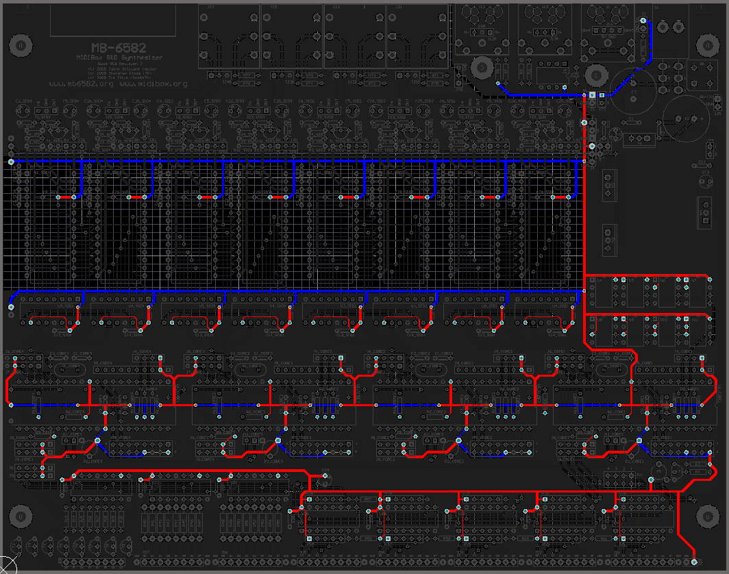
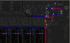
Since you say S1 pin 1 has 5V when switch is off, and not 5V when switch is on, this means there might be a short somewhere AFTER S1 pin 2, i.e. not in the power socket pads. Basically the short can be anywhere 5V and GND come close together, such as J3, J4, in the "bankstick" IC sockets, all the 100nF capacitors, etc. Check all the pads which should be connected to 5V. See picture. The last time this happened to somebody, it was in the "bankstick" IC sockets - that's where there are a lot of 5V and GND pads close to each other. If you can't find an obvious solder blob shorting pads, then you can move onto more drastic measures - cutting the 5V track to discover which "half" of the track is shorting.
-
That might mean you have a short between 5V and ground. Don't test with power connected anymore. Test continuity only, with a multimeter (i.e. beeps when probes are touching). With the switch on, you can test if the 5V pads are connected to each other, and if they are connected to ground somehow.
-
Just tell him it's for a school project and he'll fly over on his personal jet and deliver it in person. You won't have to pay VAT then.
-
I have plenty. Just email me.
-
The hole sizes are in the published FPD files for the MB-6582 panels.
-
Which soldering iron to get (was: "sammichSID Prototype")
Wilba replied to Olorin's topic in Parts Questions
I agree... I spent far too long using a cheap 25W iron when I should have bought something better... but even these fixed temperature ones are good enough to put together a sammichSID. I recommend something better because that's what I use, and it will make this and all your future DIY projects a lot easier. -
Which soldering iron to get (was: "sammichSID Prototype")
Wilba replied to Olorin's topic in Parts Questions
130 Euros? That's twice the price of my cheap temperature-controlled soldering iron. Possibly this is overkill... shop around some more. -
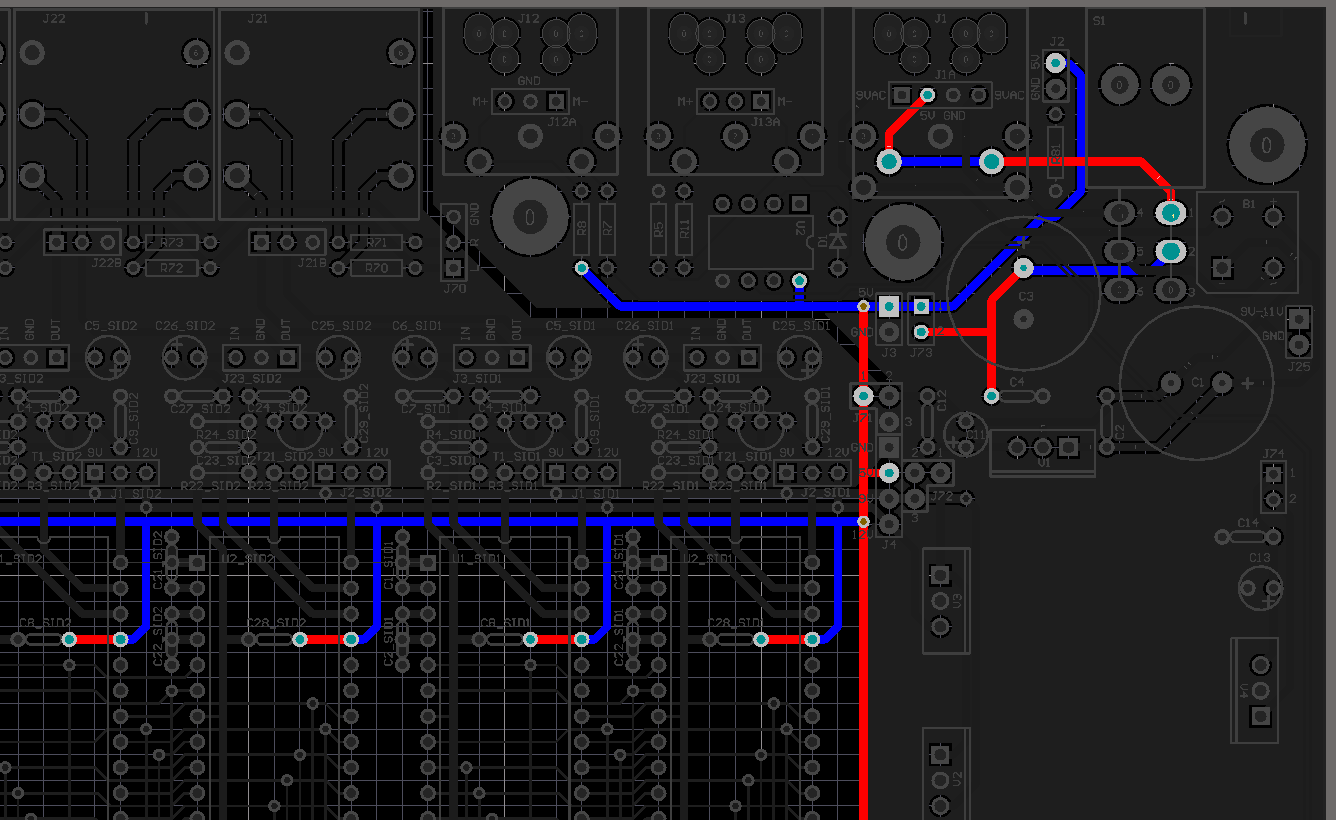
Maybe this picture will help you work out what's wrong. Just to be clear, are you testing if pins on IC sockets have 5V? And you say the pins on IC sockets have 5V, but the top pin of J3 does not? I suggest you check for 5V for all the pads shown in the diagram. Edit the image and mark which ones have 5V and which do not. It would be a lot quicker and accurate than describing it in words.
-
Maybe you forgot the bridge at J73.
-
First, the 5V connection to the CS is not used. It's there for completeness. All the LEDs are powered from the LED matrix of the 74HC595s. I don't know how not soldering T2-T9 could cause a 74HC595 to blow, since nothing would be connected to the output pins of that 74HC595. The fact that some buttons work means that 74HC595 is not blown, since you wouldn't get any buttons working if it was. Some but not all buttons working means either something wrong with one or more input pins, or something wrong with one or more of the LED/matrix column "sinks" i.e. T2-T9, the 74HC595 above it, the connection to the CS PCB... OR something wrong on the PCB itself (broken track, short). In these cases I always suggest removing the LCD from the CS PCB and checking for shorts between the LCD and the pads it touches on CS (perhaps you forgot to insulate between them). Check there are no shorts between adjacent pads that connect the base PCB to the CS PCB, or a short to ground. Likewise, you can test if the LEDs are working by first disconnecting all the 74HC595 and then applying ground to JD8 pin and 5V (through 220 ohm resistor!) to JD7 and JD6 pins. If that works, the LEDs are not dead, if it doesn't work, the problem is (probably) not on the base PCB side. You can also try putting 5V to a pin of U23 (to simulate sinking one column of the matrix) and then 5V to one pin of U22 or U21 (to simulate driving one row of the matrix)... that is with ICs removed.
-
Do you mean the MB-SEQ control surface PCB that I made? The backs of the LCD stick out a few mm past the CS PCB back... and the datawheel encoder is "panel mounted" to the PCB, so the body of the encoder is behind the PCB (maybe 5-7mm?). Plus if you use standard IDC connectors on the headers, allow for their height, plus the plastic part of the header.
-
btw congrats Phil, looks cool! Are they EL backlights on those LCDs?
-
There is a bit of confusion regarding this recent PCB/parts bulk order in January 2010. This was only a 2nd run of "bleeding edge prototypers" i.e. the people who will make their own panels/case. I posted in this thread for people to email me: This small bulk order was just for people who were going to build their own cases, and who were quick enough to reply (and were paying attention to the thread). The real (big) bulk order for people who added their names to the list here: http://www.midibox.org/dokuwiki/doku.php?id=wilba_mb_seq_pcb_bulk_order has not happened yet, and maybe never will... the original aim was to get cheap panels/cases produced, Doug Wellington offered to run this, and stuff happened, he was away for a while, and then busy with MB-808 and other things... I've since done other things (sammichSID) and not been as motivated to run a big bulk order for PCBs/parts when the only options for cases are expensive FPE/Schaeffer panels or cheaper ones made by people with CNC routers, but unable to meet the demand of this bulk order. When I polled people who were on the list, 80% said they wanted to wait for "Doug's case", so there was no point running a big bulk order until that happened. If you're interested in this PCB, and are happy to deal with the panel/case by yourself, I am sure they WILL be available again eventually, but I am not likely to run another bulk order for PCBs/parts while I run the sammichSID kit mill, and even after that, I'll probably take a break from kit mill stuff and actually make something for myself. Maybe someone else who is experienced and trusted can run another small bulk order. Maybe SmashTV can stock the PCBs so you can buy them and get the parts yourself through bulk orders. I don't know what will happen. I've done one bulk order for 37 PCBs/parts and fussylizard has done 25 or so... and combined I think we've supplied most of the experienced MIDIbox builders (i.e. the people who have built stuff before, posted often, been part of this community, or just bought stuff from me so many times before, I remember where they live). A lot of newbies who might have seen a blog picture of TK's MB-SEQ and put their name down for a "quick easy cheap" MB-SEQ solution obviously haven't been catered for. Oh well. I can't please everyone all the time. :rolleyes: I can't even find time to upgrade my MB-SEQ to V4, or even build a case for it!
-
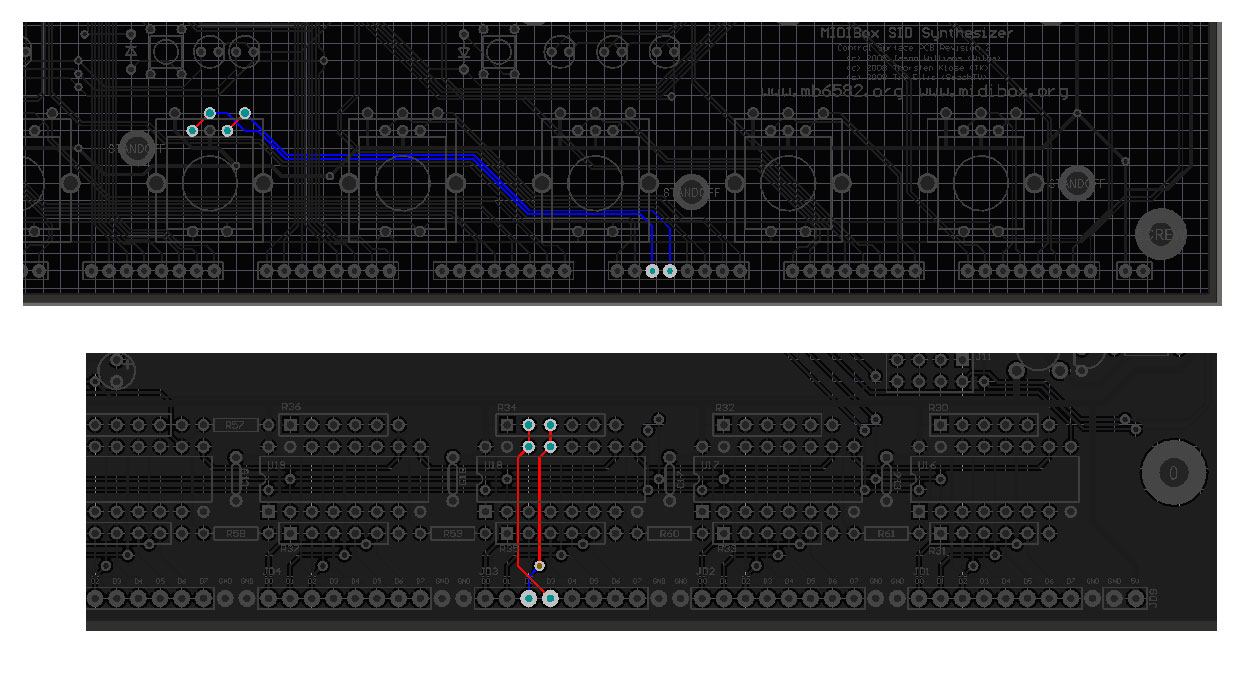
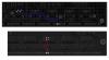
"Sync" LED just isn't used yet... I had planned for it to toggle between master and slave (i.e. LED on when it's slave to MIDI clock) but I never got around to actually coding it up (or suggesting to TK to do it). Re depth encoder, can you check you're testing the right pins? The Env Depth encoder isn't connected to D0 and D1 of J3, it's actually D2 and D3. See pic. Regarding shorting to ground... this CAN happen depending on the position of the encoder, i.e. those pins WILL short to ground as you turn the encoder, that's how it detects the turn, as one or both will be shorted to ground.
-
It's the one labeled "GND" :rolleyes:
-
All the encoders are connected to ground, the rest of the components are not, they don't need ground as they're in a combined switch/LED matrix. Perhaps the ground connection to the CS PCB is broken.
-
Encoders only going in one direction suggests that one pin is always shorted to ground. This could be at the encoder (one pin of the encoder is always connected to ground) or it could be in the tracks leading to the bottom, the cables or on the base PCB. You should be able to remove the ICs in U16-U19 (to be sure) and with power off, test continuity between ground and the two "signal" pins of the encoder, while turning the encoder, you should get "beeps" from the multimeter from both pins. Both pins will be connected to the 5V rail via 10K resistors but this shouldn't affect continuity testing between the pin and ground, I think.
-
Do you know how the 10K pullup resistors work on the DIN module? http://www.ucapps.de/mbhp/mbhp_dinx4.pdf In addition, the Core will have a 10K pullup on the input pin of the PIC, so that if no ICs are connected, there are no DIN events (button/encoder events). So perhaps when there is no IC in U16, it "works", but when you put an IC in U16, some "garbage" going into U16 from U17 is making lots of false button/encoder events. Normally this should not happen if there is only one IC in U16, as either resistor R61 or the 5th resistor in resistor network R30 (the pad that is outside the white rectangle!) will pullup the input into U16... i.e. the data being shifted through U16 from U17, U18, etc. Perhaps something is wrong here... so that pin 10 of U16 is "floating" or always 0V, causing garbage to get into PIC. Check you are using 6-pin resistor networks, and they are correctly positioned (pin with dot marking is at the left end, in the square pad, next to the R30 etc. label). Check also if R61 is not shorting to ground, or U16 pin 10. If you assume the IC is good, this is the only thing I can think of at the moment... because when the IC is out, you do not get the garbage... and if the IC is in, then the events you get are not "encoder" events and more like button press events, which can only happen with garbage from U20, i.e. from garbage data going into U16, not from false triggering from U16's input pins which connect to the CS PCB.
-
The MB-6582 does use BC547 for sinking both common cathodes of LED "columns" (up to 16!) and also the switch in the switch matrix. I just posted why here: They aren't always required, it all depends on how many LEDs you want to use, their brightness at low current levels, how much current will be sinked by one DOUT pin, etc. You can get away with no transistors (re sammichSID) or play it safe and put them in. I used BC547 instead of Darlingtons because the collector emitter voltage of Darlingtons would be too high for use in a switch matrix, i.e. the voltage at the DIN input if I used Darlingtons would be close to or maybe over the logic low voltage threshold, depending on current sinked through the Darlington.
-
There are current limits on the output of each pin of the 74HC595, and also a current limit for sinking current. Assuming you have your matrix arranged in common cathodes in a column, connected to a 74HC595 pin, when that pin is outputting low (0V) and "selecting" that column, there's only so much current that it can sink... therefore depending on the output current (i.e. how many LEDs are turned on), this may affect how bright the LEDs will be. One fix for this would be to increase how much current can be sinked by one column, by using a transistor like BC547 with base connected to the DOUT pin (via 1K) and the collector connected to the common cathodes and the emitter connected to ground. You would also need to invert the outputs on that DOUT, so a high output will "select" that column and sink current through the transistor collector. Thus you can sink 100mA per column of LEDs, and are then only limited by the output current of the 74HC595 (i.e. the same as a LED connected directly between DOUT pin and ground). This is what I did on the MB-6582 base PCB, should you want to see an example (see the transistors in the lower left corner of the PCB).
-
Problems with MB-6582 Testtone upload *FIXED*
Wilba replied to JaseM's topic in Testing/Troubleshooting
I meant that I tested MIOS Studio MkII by uploading setup_mb6582.hex to my MB-6582 because it happened to be connected at the time. Always upload setup_mb6582.hex to MB-6582, setup_sammich_sid.hex to sammichSID. -
What he said.
-
Problems with MB-6582 Testtone upload *FIXED*
Wilba replied to JaseM's topic in Testing/Troubleshooting
Were there any error messages in the upload progress window? You can try uploading MIOS 1.9g again to the PIC. You want to upload file: \mios_v1_9g\pic18f4685\midi\mios_v1_9g_pic18f4685.hex in the MIOS 1.9g distribution: http://www.ucapps.de/mios/mios_v1_9g.zip NOTE: I just tried it with MIOS Studio MkII Beta 3 and I get black bars too. I think this beta is broken. But some time really soon now TK will fix it :) Sorry, my bad... my original MB-6582 is configured to use the alternate LCD driver (8bit instead of 4bit) which means I get black bars if just MIOS is installed, needs an app with the LCD driver. I uploaded setup_mb6582.hex and it works. -
Installing hex files to PIC outside of CORE...
Wilba replied to JaseM's topic in Testing/Troubleshooting
I was about to suggest this too... it works for me with Windows 7, despite looking like a Mac app :sick: -
no problem, just don't forget to nag.