

Wilba
-
Posts
3,310 -
Joined
-
Last visited
-
Days Won
2
Content Type
Profiles
Forums
Blogs
Gallery
Everything posted by Wilba
-
Wouldn't it be better if the pad contacts were circular like the SparkFun ones? Surely there would be enough room for a 3mm bicolor LED. The Livid ones are my current favourite. If I ever get time to build my own BLM16x16, I would probably do a sort of "modular" PCB using the Livid pads, 8x8 plus extra 8+8+1 X XXXXXXXX X XXXXXXXX X XXXXXXXX X XXXXXXXX X XXXXXXXX X XXXXXXXX X XXXXXXXX X XXXXXXXX X XXXXXXXX [/code] then chop off the extra buttons on three of the boards, join together to extend it up to 16x16. Maybe each board has mounts along all four edges, so after chopping, you'd still have mount points for the top/right edges of the joined PCBs. It might need a bit of extra wiring here and there to make it work, and something like the "stitching" method on my SEQ CS PCB proto. [i][color=#FF0000]* Wilba scratches beard[/color][/i] hmm....
-
sealion: You have a dead SID. Get a replacement. This should be no trouble, I know who you got them from, but if it is, email me.
-
Just noticed this... Bliptronome kit... convert Bliptronic 5000 to monome clone. http://www.straytechnologies.com/bliptronome-kits-are-here/
-
My sammichSID is complete and 100% working at first boot
Wilba replied to Filch's topic in MIDIbox SID
That happens to me too, with some LCD/PSU combinations. Unfortunately, sammichSID design is a compromise between overall size, heatsink size, overall current draw, LCD current draw (brightness), PSU voltage/max current, parts cost, etc. Powering the LCD from the (potentially) unregulated input voltage is a big hack, but it doesn't generate more heat out of the voltage regulators and heatsink. If SIDs didn't need dual voltage, it would be a lot simpler *sigh* -
Send the clicky 6582A back, I will send you a new one.
-
The oscillators are digital. Frequency is set by a 16-bit register, which is relative to the system clock (standard 1.0 Mhz). The waveforms are then generated by an accumulator, which produces the sawtooth waveform. Some other digital tricks are done to produce the other waveforms. In case you're interested, here's an article with Bob Yannes, creator of the SID: http://www.joogn.de/sid.yannes.html
-
If you want to reproduce this same sound in a patch (after startup), this is what the patch is... converted from the registers being set: Volume set to 15 Filters off. OSC 1 Pulse waveform, Attack 0, Decay 0, Sustain 8, Release 8, Pulse Width 800, everything else zero/off. OSC 2 and OSC 3 are off. This is almost identical to the init Lead patch... looks like only Sustain and Release are different. It would be interesting if you could reproduce the click in a patch, or not, and then know if it's a startup-only issue or your SIDs being clicky. So the 2x 6582A that came with the sammichSID don't make this clicky sound?
-
My sammichSID is complete and 100% working at first boot
Wilba replied to Filch's topic in MIDIbox SID
So it could have been bad contacton the P1 wiper, or current draw close to current supply limit. If you're happy with the brightness where it is, then it ain't broke, don't fix it, nothing to see here move along.... ;) -
Something does sound a bit wrong there... and also, when you look at it in a sound editor, you've got lots of strange stuff going on. Your left and right channels aren't matched, and it looks like it's almost clipping it's so loud. Compare it with the sample I made and tell me what you think. mb-6582_startup_wilba.wav
-
My sammichSID is complete and 100% working at first boot
Wilba replied to Filch's topic in MIDIbox SID
Flicker/dimming is not normal. It could be a bad solder joint in the backlight circuit. Check solder joints in that area. i.e. J16 pins 15,16 (or equivalent on LCD), T1, JR4, R4, P1, JBL. Maybe the P1 pot wiper is making poor contact. Try turning it a little. Also JR4's shunt might be making poor contact. It could also be a current supply issue, but I think you posted a link to a good PSU so it's probably not that. Check if it still happens when P1 set to 1/3rd brightness (instead of 1/2).... or if you remove the SIDs.... or if it happens when sammichSID isn't doing anything (i.e. take out the PIC). -
MIDIbox Of The Week (Phunk-Box: MB64e of Phunk)
Wilba replied to phunk's topic in MIDIbox of the Week
Now you're just showing off... :rolleyes: SRSLY :drool: -
WAVs or it didn't happen :D
-
I think you may have multiple issues. You will need to sort out either the control surface issues, OR the SID issues. Both might be related to the same problem. I would probably say the SID issues are easier to resolve, because there's less things to check, only one PCB where there might be a problem. You can try the testtone app with the SIDs removed. This helps identify if there's a problem with the audio buffers (i.e. the noise comes from them). Take out the SIDs and put a 1K (or similar) resistor between socket pin #8 and #27. Make sure you connect it in the right pins! Pin #27 will NOT have 9V! Connecting 9V to pin #8 is BAD You should get 1kHz out of the audio outputs, this will probably be at max volume level too. If you don't, there's a break between pin #8 and the PIC, OR the audio buffer is the problem. You can narrow this down by connecting pin #8 from the left SID socket to pin #27 of the right SID socket (and vice versa). BTW are you sure your audio is working? You are using a stereo plug? The interconnection test is supposed to validate that the PIC->SID connections are correct, as well as connections to the two 74HC595 ICs below the SIDs. If you're not getting the right voltages when you send the Mod wheel message to change which pin is high (for the pins connected to the 74HC595), then there's some issue with the three serial data lines between the PIC and the 74HC595. Check for bad solder joints, shorts, breaks, etc. between the PIC and the SID sockets, 74HC595 sockets. AFAIK a high noise floor might result from either the audio input not being grounded (some issue with the audio input socket, or tracks between there and the SID pins)... OR if setting the volume registers in the SIDs isn't working, because the data lines aren't working. So until you get the interconnection test working properly, I would say not worry about high noise floor, that might be fixed by fixing the interconnections. Also, if you are still observing high noise floor when SIDs are removed, then it obviously has nothing to do with SIDs or the interconnections... some issue with voltages like the 9V supply, or ground, or the audio buffers. Try to identify if the noise is on one or both channels perhaps.
-
Take off the control surface PCB. You say pressing buttons has some audible effect, this shouldn't happen. There are two test apps you can use. http://www.ucapps.de/mios/mbsid_interconnection_test_v2.zip Testprogram for the interconnections between Core and SID module of MIDIbox SID (read the README.txt file for the usage) http://www.ucapps.de/mios/mbsid_testtone_v3c.zip Just plays a 1kHz triangle wave on the SID - nice for testing the audio output without the need for a MIDI sequencer or keyboard. With the new v2 version, both MBHP_SID modules connected to a core are initialised. In addition, a 1kHz square wave will be generated on the CS pin (#8) - see xxx for additional informations.
-
You need to troubleshoot the MIDI. http://www.ucapps.de/howto_debug_midi.html You can't tell yet whether it's MIDI In or MIDI Out that is the problem. i.e. MIOS Studio sends SysEx and expects SysEx response. If MIDI In doesn't work, the PIC won't respond. If MIDI In works, but MIDI Out doesn't, the PIC responds but it's not received by MIOS Studio. Do the loopback tests etc. The how-to is for Core8 module, but you can use the MB-6582 base PCB diagram to match things. Don't forget that J11 controls which PIC Tx pin connects to the MIDI Out (via the 220 ohm res).
-
MIDIbox Of The Week (Phunk-Box: MB64e of Phunk)
Wilba replied to phunk's topic in MIDIbox of the Week
Awesome. How you you make the wood parts? (especially the bevel). I want to make stuff out of wood but I am clueless. -
What kind of SIDs are you using? Is the shunt in JP correct for your SID type? Do you have the filter capacitors (C1L, C1R, C2L, C2R) installed in the machine pin strips? Are they correct for the SID type? Are they in the right holes?
-
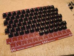
I posted in about what I was working on: So rather than clutter that thread, I'll start a new one. This is my stupid hacky experimental jammer keyboard using Cherry MX keyswitches. Inspiration is from here: http://musicscienceguy.vox.com/ You can read up about jammer keyboards, the Thummer, Wicki-Hayden layout, etc. This is intended to be a jammer with Wicki-Hayden layout, but you could make it do any other layout, like Janko. This is my first attempt. The more refined version uses a larger, U-shaped contact glued to the actuator, but is essentially the same. The contacts on the side of the switch are two pins from a female header. These are easily pulled out from the bottom and look like a two-pronged fork. I glue these to the side using superglue, then cut one prong off each and bend the other one down. They are placed lower than shown in the above photo, so after the bend, there's clearance between the tip and the cylindrical part of the keycap which goes onto the keyswitch actuator. The contact on the keyswitch actuator is made from the metal disc inside a typical 12mm tactile switch... it's slightly concave so when in the tactile switch, it's the part that acts as the switch spring and which makes the contact (shorts the switch pins). It's just the right thickness, thin enough not to interfere with the keycap, stiff enough to cut into a shape and not wear away. I cut the disc in half, then with the half-disc, first cut a notch to match the actuator, and then trim the other three sides. I gradually trim it to the exact size of the actuator - it's too small to do any kind of measuring and marking, so I do it by eye and then test fit it until it's right, or until I've cut too much away and have to start again. I then superglue it on the actuator, making sure you don't get any on the top, or up the actuator shaft. This is why I use a U shape now, instead of the thin strip in the first photo - the U shape means more surface area for the glue, and also makes it easier to align it when you're gluing it, i.e. the "perfect fit" means it won't slide out of position during gluing. What's important is getting it as big as possible, so the contacts have a place to touch it, yet it's not hanging over the edge of the actuator and rubbing against the hole (and getting pushed off during a depress). In case it isn't obvious, you do all that with the switch disassembled, wait until glue has fully dried, then put it all back together, make sure the keycap won't rub the two top contacts, do lots of tweaking until you get good contacts (test using a multimeter). The spring of the Cherry MX will push the actuator (and the metal contact) against the other two contacts, and since there's some slack in the actuator shaft, it will "touch" against both the top contacts sort of evenly. I'm not really explaining it right... basically it works, if you tweak the top contacts so they are the same height and a little bit lower than where the actuator wants to be when not pressed. It's not a very easy process, still at the experimental stage. There might be a better, easier way to do the same thing. This just happens to be the way I did it first, because it's what I had on hand, hundreds of tactile switches lying around, and a few female headers. It's not that cheap either, salvaging a bit of metal out of a 30 cent switch... but then maybe that's not too bad... Worst case guestimate, I've used 100 tactile switches for 96 keyswitches, so that's only $33. I'll pay that to add velocity to a keyboard. Anyone wanting to do the same thing needs to experiment and learn their own method of doing it, how much glue to use, where to position the bits, esp. how to cut the discs, since cutting is done by hand. I mean, I could write up how I do it, but then if you follow that process, it might not work for you. It works for me because I'm crazy and have good eyesight and can cut 0.1mm slivers off a tiny piece of thin metal that I hold down with a finger. You might be half blind with fat fingers and my process would be useless. DIY! It's not rocket science. In all likelihood, it would have been quicker and only marginally more expensive to buy an Axis-49, connect it to a Core32 and run my own firmware to get Wicki-Hayden layout, instead of requiring some PC software to remap the notes. That thing seems to have good travel, hex keys, velocity sensitivity, rubbery goodness. Why did I bother then? What I'm doing is a hacked together experiment... I mean, it will work, it will have velocity sensitivity, it will even have blinken blinken.. the experiment is more to do with the ergonomics... does an isomorphic (jammer) keyboard need hex keys or round keys? can you use computer keyboard keys? does having the actuation point half-way down the travel (instead of at the bottom) make a difference to playability? does familiarity with PC keyboards translate into a shorter learning curve? does using a computer keyboard keyswitch, preferred by typists that prefer not to "bottom out" when typing, result in some advantages when used in a music keyboard? I'll be happy when it's put together and works, I'm just not saying now that it's going to be anything special, or some great leap in keyboard design. It's just an experiment. At the very least, it will be something interesting to jam with and help me learn music without being held back by the classic piano keyboard layout.
-
The 74HC165 on the right, including the resistor networks next to it. You can follow the traces on the top side to where they connect to the IC.
-
Check the encoder pins are not touching the heatsink. A poor solder joint might fail after five hours, or anytime after soldering.
-
There are no stupid questions, only stupid people. :wink: Quote from here: It doesn't go into specifics of the 4-bit vs. 8-bit thing. Since the two PIC18F4685 pins for the CAN bus are the same as have been used by MIDIbox Core modules for J15, then by default, MIOS on PIC18F4685 uses 4-bit. Conveniently, this means you only need to leave four pins of J15 open and then the same cable you would use for 8-bit will also work... i.e. if the unused 4 data lines are left open at Core:J15, then the LCD will work in 4-bit mode. This is what I've done on the MB-6582 PCB. So you should just make the cable as if it's intended for 8-bit, according to the "older" wiring diagrams. Since you'll probably be using a 16-wire ribbon cable anyway, it doesn't make much difference, and it's easier to follow the wiring diagram if you forget about which four wires won't be used.
-
... and here's one I prepared earlier :wink: ... and even when I thought I was being original... someone else has used Cherry MX in a music keyboard:
-
From the album: Wilba
© © 2010 Jason Williams
-
I swear I suggested using Cherry MX switches before.... surely I did.... Oh yes, I did... You can add extra contacts to make them velocity sensitive, although this is fiddly and takes a long time. Here's my first "proof of concept". I've since improved the design a little.
-
MB-6582 Front Panel from Schaeffer / FPE with minor defects - Poll
Wilba replied to Smithy's topic in MIDIbox SID
Coincidentally, I just got an email from Front Panel Express to complete an online customer survey and received a $20 discount on my next order.
