Wilba
-
Posts
3,310 -
Joined
-
Last visited
-
Days Won
2
Content Type
Profiles
Forums
Blogs
Gallery
Everything posted by Wilba
-
Installing hex files to PIC outside of CORE...
Wilba replied to JaseM's topic in Testing/Troubleshooting
MIDIbox firmare comes in three parts - there's the bootloader which is burned onto the PIC, and contains enough code to allow uploads via MIDI. Then MIOS, the "operating system", can be uploaded via MIDI (or pre-installed by SmashTV etc.). Finally, the application itself, which is the .hex file in a release, can be uploaded via MIOS Studio. The application .hex file, therefore, is only part of what is on the PIC, if you tried to burn just that .hex file onto the PIC, the parts where the bootloader and MIOS should be will just be blank and it won't work. You can upload an app to a PIC and then dump the whole PIC memory to make a complete .hex file, which then can be burned with a PIC burner. (or ask someone else to dump the complete .hex file). I use PICPgm software and a JDM burner I bought off eBay. Previously I used a self-made JDM burner but I "upgraded" to one with a ZIF socket as now I have to burn a lot of PICs. So yes, it can be done... but it's not the solution to a MIDIbox that can't receive firmware uploads via MIDI. Even if you got the MIDIbox SID app installed by burning, the patches can only be uploaded via MIDI (through a patch editor), and if your PC/MIDI interface is having SysEx comms trouble then patch uploading might also have trouble. -
Problems with MB-6582 Testtone upload *FIXED*
Wilba replied to JaseM's topic in Testing/Troubleshooting
You should be able to follow the troubleshooting guide, to both validate that MIOS Studio on the netbook is functioning correctly... that it is sending MIDI to the PIC. You need to try a loopback with just the cable between MIDI In/Out (PC end) then try taking the PIC out and shorting between the Tx and Rx pins (see Troubleshooting page). Other things that could be wrong with sammichSID: Missing jumpers or bad solder joints on JMI and JMO Bad solder joints on MIDI sockets. Missing/faulty 6N138 optocoupler. You shouldn't try to upload again until you can test MIDI In on the sammichSID by sending it LCD commands through MIOS Studio (see sammichSID build guide). You won't be able to rule out hardware faults until you can prove MIOS Studio/MIDI is working to and from your MIDIbox hardware. -
These questions should be answered on the wiki page, but they aren't. http://www.midibox.org/dokuwiki/sammichsid If only I had a slave to do all these mundane tasks like updating the wiki... Yes. From batch #5 onwards, all sammichSID kits will come with either: yellow-green high-power backlight LCD and green LEDs. white-on-blue low-power backlight LCD and no LEDs. (I have 25 or so, but not many people want them, so they'll last a while yet) no LCD and no LEDs. Current kit price includes LCD and LEDs. If you choose an option without LCD or LEDs, I deduct the price difference. I'm currently packing batch #4 (nearly done). There'll be a delay while I order more PCBs and do a stocktake on what parts I have and need to reorder. I may need to ramp up my production of kits, maybe do 50 kits at a time, so I can aim to get the next 100 kits (batches #5-#8) shipped before May.
-
Some more to think about: a good, simple circuit for getting fast touch on/off from a SoftPot. It's designed for CV/gate control, so it has a sample and hold section which might be redundant for MIDIbox, but a simpler alternative to the Appendage circuit when all you want is one analog output from a ribbon to feed into a microcontroller. http://www.electro-music.com/forum/viewtopic.php?t=32246
-
I got mine here: http://www.altronics.com.au/index.asp?area=item&id=H6016 If you're unable to find them locally, I suppose I could get some next time I'm at that store and post them to you... but I really don't want to start a bulk order for them, sending four each to every MB-6582 builder. Postage would be cheap as I could pack them flat in an envelope... maybe only 2.20 AUD postage for four. I'll preemptively put a limit of one parcel per country. :D
-
Problems with MB-6582 Testtone upload *FIXED*
Wilba replied to JaseM's topic in Testing/Troubleshooting
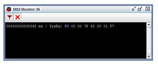
8 bytes is correct, it should be "FF 00 00 7E 40 00 01 7F" Isn't there a way to see the actual bytes with the MIDI Monitor program? Maybe some SysEx receive dump function, or raw MIDI In data window? You can also try MIDI-OX with Windows, that will also validate the SysEx data is correct. I think it's safe to say that your sammichSID is sending the upload request, and assuming the sammichSID MIDI In is also working, you only need to sort out the Mac/Java/MIOS Studio issues, or maybe work out why it isn't working on the PC, maybe that's easier to fix. I'm not sure what you mean... the problem lies with MIOS Studio being unable to send and receive MIDI data through your Java/MIDI library/MIDI Interface... you need MIOS Studio to send the firmware in SysEx dumps to the PIC, and have the PIC send back acknowledgement messages with checksums, so you know it uploaded correctly. -
Problems with MB-6582 Testtone upload *FIXED*
Wilba replied to JaseM's topic in Testing/Troubleshooting
He said he already bought Mandolane. Maybe upgrading Java will help. What version Java do you have installed, jbartee? -
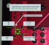
I'm a little bit puzzled by the second set of bridge rectifier measurements, since if the black lead is on ground near C4, then it should be the same as the first set. The first set of bridge rectifier measurements look OK. What I also don't understand is how you are not seeing the 11.96V at the "orange" dot positions, since the bridge rectifier "+" output should be directly connected to the 7809 voltage regulator input (where you marked with orange dot) and also the other places you marked with orange dots. These should all be roughly 12V (i.e. what the bridge rectifier outputs). Maybe you have a short to ground somewhere around the bridge rectifier or the "12V" pins... maybe even heatsink compound or the heatsink is shorting pins of the 7809 voltage regulator. Without ~12V going into the voltage regulator, you won't end up with 9V or 5V, as the voltage regulators can't work. So... first check if the bridge rectifier "+" output is connected to the 7809 input (you can see the trace going between them on the top side). If it's connected (~0 Ohms resistance), then it's maybe a short between 12V and ground. I don't want to suggest taking out the 7809/7805 just yet, but it might be required as part of working out where it might be shorting. Can you please retest the values on the bridge rectifier with black lead on J2:GND (near C4), and ALSO J20:GND (near 7809) and take care to put the lead on the correct pin, they are the ones without a dark circle around the pad, since the pad is connected to the ground plane. Check also the resistance between the 12V pins (aka. "orange" dots in YOUR picture) and various GND pins.
-
Problems with MB-6582 Testtone upload *FIXED*
Wilba replied to JaseM's topic in Testing/Troubleshooting
Try http://www.snoize.com/MIDIMonitor/ to see if you get the upload request. If so, then it's the "Java-based MIOS Studio + crappy Mac Java MIDI library" issue. I'm not sure exactly what you need to do to fix this... it's been discussed before on the forum, but I don't know exactly what fixes it. It might be a Java version upgrade or installing a MIDI library. It might be best to start a new thread about this issue so people with Macs can share and find solutions. TK is working on a MIOS Studio that doesn't use Java, specifically to solve all these "Java MIDI on Mac" issues. A quicker solution might be to try doing your uploads using a borrowed PC. -
Problems with MB-6582 Testtone upload *FIXED*
Wilba replied to JaseM's topic in Testing/Troubleshooting
OK so there's some issue with MIOS Studio on your PC. What is your configuration? i.e. O/S, MIDI Interface, etc. -
Problems with MB-6582 Testtone upload *FIXED*
Wilba replied to JaseM's topic in Testing/Troubleshooting
Until you validate that your PC's MIDI In is working, there's no point searching for a hardware fault. -
Problems with MB-6582 Testtone upload *FIXED*
Wilba replied to JaseM's topic in Testing/Troubleshooting
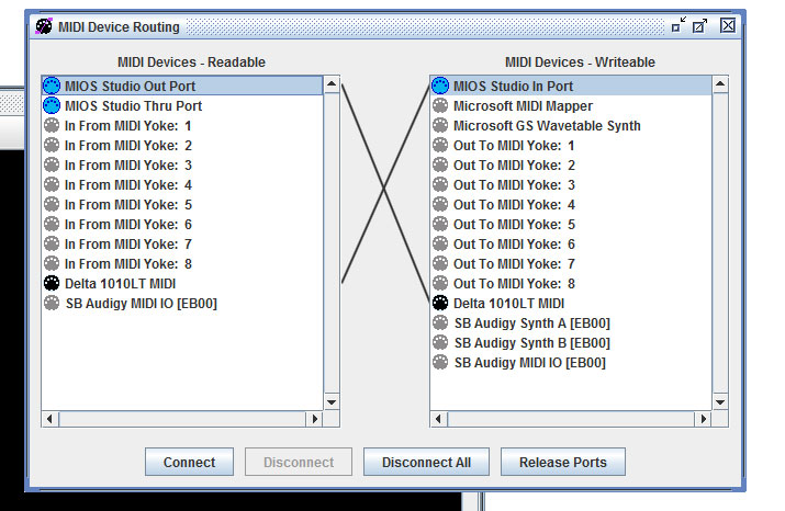
The fact that you're having the same problem on both the MB-6582 and sammichSID suggests something not right with your setup. Perhaps. It could also be a hardware fault on both. You can't rule out setup fault until you've tested that your MIOS Studio MIDI In monitor is actually showing messages received from your MIDI interface. For sammichSID, check you have shunts correctly installed in JMI and JMO headers. Are you sure the MIDI cables are connected correctly and the cables are working? Can you plug in some other MIDI controller and receive messages in MIOS Studio MIDI In monitor? Have you correctly routed the MIDI in MIOS Studio? Do you get an upload request when you power on? Have you done a loopback test? (i.e. send notes with MIOS Studio keyboard, same messages in MIDI In/Out windows) With MIDI cable between PC MIDI Out and PC MIDI In? With PIC removed and shorting Tx/Rx pins? (on sammichSID, you can remove shunts in JMI and JMO and short middle pin of JMI to middle pin of JMO). So instead of doing these things like I suggested earlier, you're asking if there's a way of bypassing your broken setup... there is, you can convert a hex to a SysEx dump, but this is not advised, there is no feedback so you won't know if the upload was uncorrupted.
-
Definitely not... you're doing stuff that I've planned to do for years but haven't due to too many distractions... :whistle: Well... I did actually experiment with the PAiA "two-touch" ribbon controller circuit but it didn't work as well as I'd hoped... there was an issue of the output voltages doing strange things when you released the touch, I never resolved those issues. Then when another guy was developing his own ribbon controller and apparently solved this issue with some analog electronics beyond my level of expertise (not that I have much anyway), I was waiting for the results of that, and then buy a PCB... but I'd sort of lost interest (and funds) by the time the PCBs were available. IMHO that project is good but quite overkill for me, since I probably only need a single touch point value to be sampled. I could probably distill some of the debouncing ideas out of the schematic and use them eventually... but maybe I won't need to if your voltage regulator idea gives a reliable gate on/off from touching. It sounds from this statement that you're limited by the 3.6V... i.e. that you can't get the voltage range across R2 for fear of driving the analog input into the STM32 higher than 3.6V. Maybe what you can do is just add a protection diode to the STM32's analog input so the "open circuit" voltage can swing higher. One thing I recall from the MIDIbox Extensions page is the "3 LFO Extension" example, which shows how you can make some hardware LFOs running with +12/-12V outputs and connect them safely to the PIC analog inputs. The schematic is pretty self-explanatory... by putting some diodes between the analog output/PIC analog input and the rails (5V/0V), it will clip the voltage range to -0.7V to 5.7V. Note also the 1K resistor to prevent high currents. Maybe this same idea can be used for your circuit, so using a diode between the 3.6V rail on the core and the analog input, plus the 1K resistor, should limit the voltage to 4.3V. FWIW... Figure 54 of the STM32 datasheet shows the analog inputs already have diodes to Vdd/ground to prevent damage from the input voltage being outside the Vdd/ground range (not that I suggest you leave out external diodes). Just out of interest, do you notice any voltage "noise" as you release touch? If you have basic note on/off and pitch, then when you press and hold the ribbon, you should get a fairly constant "pitch", when you release, does the "pitch" change drastically before the "note off", or stay as just as stable as while it was being pressed?
-
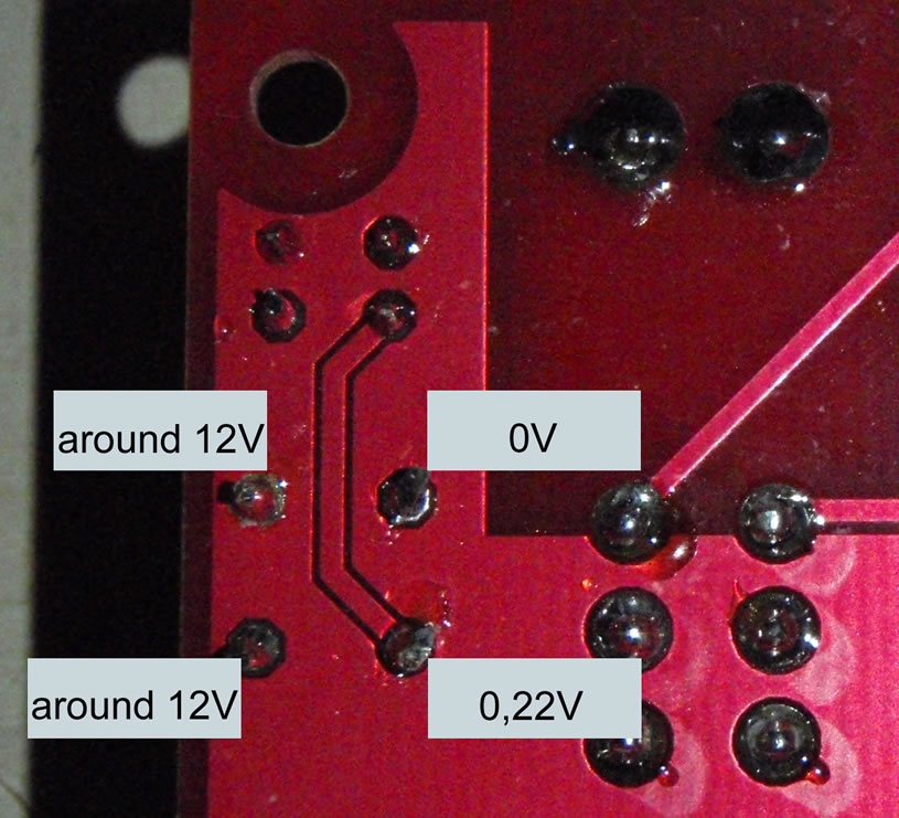
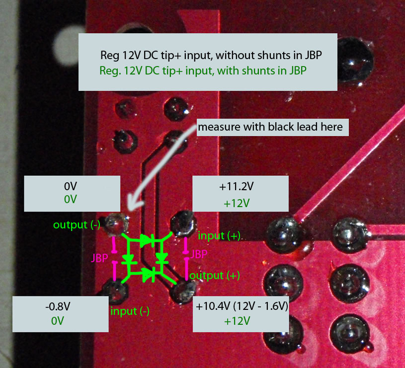
I don't think the bridge rectifier is dead. Compare your measurements: with mine: The fact that you're getting "around 12V" on the ground pin of the bridge suggests your black lead of the multimeter is not also on ground, which it should be so you can actually get meaningful results. I can't tell now what "around 12V" means because it's "around 12V" above something. Take measurements again with the black lead of the multimeter on the ground pin always.... EXCEPT when you want to check polarity/voltage of the input power, then measure with black lead on "input (-)" and red lead on "input (+)"... with power switch on, it should be the same as measuring it from the plug. Note also that the 0.22V value suggests you also have not put shunts in JBP, which you need to do if you're using regulated 12V DC and want to use 6581 SIDs. If you are not using 6581 SIDs, then you don't need shunts in JBP. As you can see from my pic, adding the shunts will short two of the diodes inside the bridge rectifier, so that you don't lose 1.6V and thus the SIDs will get the full 12V coming from the input. HOWEVER for that to work, the input power needs to be tip positive (+) otherwise the other two diodes will be used to reverse the polarity and you will only get 10.4V. Send more measurements and I can help you more.

-
MB-6582 Need advice on troubleshooting audio buffer
Wilba replied to highrider's topic in Testing/Troubleshooting
It's OK to upload MIOS 1.9g to all PICs. When I said try testing with an arp sequence, I meant a patch which has its own arp sequence... or any patch that will vary the sound over time... so when you hold down a keyboard key and it gets stuck on, you know the PIC is still running because the sound is still varying (as opposed to the SID being stuck with it's oscillators at constant frequencies). However, since you don't have any control surface yet, it's hard for you to setup a good test across the multiple PICs. The patch banks are uploaded to the 24LC512 ICs not the PIC, and are only connected to the master PIC when in the #1 slot, they won't be available when the PIC is elsewhere. I don't think your PICs are broken... use the changeid program to swap PIC 00 with PIC 01... then try the new PIC 00 in the master slot. You really should connect an LCD, this can show you if there's a problem with the CAN bus and also let you connect the LCD to any Core and check it's still receiving MIDI by sending LCD commands with MIOS Studio. Right now you're trying to debug with no LCD and no control surface, it's too hard... make things easier for yourself! -
The mouser one looks OK... right length, pitch... I think someone else has used these before.
-
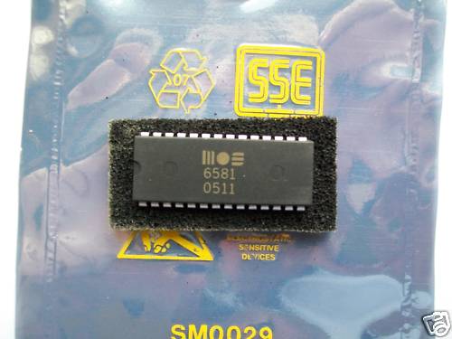
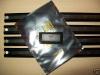
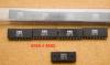
FACT: This seller DID sell new old stock 6582A SIDs in the past, with the same datecode as the stock I sell. HYPOTHESIS: He probably got them from the same broker I got mine. The broker did tell me they supplied some 6582A stock to the UK, which coincides with when this seller was selling 6582A SIDs. FACT: I have NEVER seen an example of datecodes on GENUINE not-remarked SIDs being inaccurate. On remarked SIDs, they are wildly inaccurate because someone has no idea what number should be there, so they either copy a genuine SID, or make it up. Sometimes they even get the part number wrong. HYPOTHESIS: SIDs marked with a datecode of "0511" are MOST LIKELY remarked, despite looking genuine and purchased in "tubes". Of course these remarked SID suppliers are going to ship the SIDs in tubes, and they will look very much like genuine not-remarked SIDs, the pins will be straight and made shiny, the labels reprinted. It's not totally impossible that some 6581 SIDs with "0511" datecodes were produced, but why only 50 or so? FACT: People have been buying up all the "new old stock" of SIDs, both 6581 and 8580, for over ten years. It is highly unlikely that another couple hundred SIDs have been found somewhere and only recently been put on the broker market. HYPOTHESIS: Any large quantities of "new old stock" SIDs are most likely remarked pulls. I AM NOT suggesting this particular eBay seller is dishonest... these SIDs were probably sold to him by some shonky Chinese broker as "genuine new stock" and they probably look better than the remarked crap I've seen so it's not immediately obvious that they're remarked. I got suckered into buying some remarked stock before, as you can see from the photo. I also didn't believe they were remarking 8580 or 6582A but I was wrong. I took a loss on that deal, and managed to recover some of the money through my usual broker physically bringing the crap chips back to the vendor and getting a cash refund, not including the courier costs for the shipment. These brokers who sell remarked chips are total assholes. They KNOW they are selling remarked chips, and then stall on refunds, start a new company, and also typically only deal with companies outside China, so they can get away with this shit without any consequences. Preserving the pics from the auction, for future reference!

-
MB-6582 Need advice on troubleshooting audio buffer
Wilba replied to highrider's topic in Testing/Troubleshooting
It should not matter whether you upload directly to each PIC or via the "cloning" method, both will result in the same firmware on the PIC... perhaps uploading directly is better because in MIOS Studio you get feedback (i.e. CRC checks on each block). This is probably happening during "cloning" via the CAN bus too, but there's less confirmation that everything is OK. I don't think your PICs are broken... if you really want to test things, you could use the changeid program to make another PIC ID=00 and try that in the first Core. Holding the note/going mute: How exactly are you testing that the other PICs stop working? i.e. what is your current setup, how do you make all four PICs/SID engines operate? The problem could be related to the CAN bus (i.e. master PIC->slave PIC communication fails) OR maybe even MIDI In to the slaves stops working (so you get a stuck note because Note Off is never received, or mute because Note On is not received anymore). It's also possible that the PICs stop working completely... you should try a patch that has some kind of modulation so when it "stays on", you can tell that the synth engine is still running. For a simple patch without modulation, the SID might still be playing the last note while the PIC has stopped and you wouldn't know. So you should try something like an arp sequence so you can hear it still "working" and know the PIC is still working (as opposed to stopped completely). -
MB-6582 Need advice on troubleshooting audio buffer
Wilba replied to highrider's topic in Testing/Troubleshooting
It would probably be easiest to just replace the transistor and see if the problem is fixed, thus proving it was probably the transistor at fault. It's highly unlikely any of the other components are broken, as they're all resistors and capacitors which don't often fail from soldering too long, unlike transistors. -
I can't see how you can get "U1 SID 1 no sound" in the first test (without SID) and then "U1 SID 1 good" in the second test (with SID). Try the "good" PIC (01) in each slot, and two "good" SIDs, do both tests again. Swap SIDs as well to prove it's not the SID. Repeat with another PIC, if the results differ, then the PIC is the problem, on top of other problems.
-
Based on how many people make mistakes when putting together something relatively simple and thoroughly documented like a sammichSID kit, do you think it is wise for me to encourage people to wire up a transformer to a mains plug? If people want to win a Darwin award, they can do it without any help or suggestion from me... :tongue:
-
I would advise not to use ULN2003A (i.e. darlington transistor array). When these are fully sinking current, the voltage at the collector (i.e. collector-emitter voltage) when fully saturated MAY BE higher than the logic level low voltage of the 74HC165. This is why I used discrete BC547 transistors in the MB-6582 - 1K resistor between output pin and BC547 base, collector to common cathode "row", emitter to ground.
-
I would think finding a good power supply/plugpack (i.e. 12V DC non-switchmode) is harder to find than silicone heatsink compound, since they've been phased out in many countries and you can only buy new switchmode ones. If anyone has any good ideas about making MIDIbox SID work with a switchmode plugpack (i.e. eliminating the AC hum) then please share!
-
No, the suffix does not matter, I think it relates to different hFE/gain values, but in this context, the transistor is either fully conducting or not conducting.
-
Don't forget that YOU need a REGULATED 12V DC and not switchmode (because you want to use 6581, otherwise unregulated would be OK). Good luck with that :thumbsup: They stopped selling them here, it's all switchmode now :mad: