Wilba
-
Posts
3,310 -
Joined
-
Last visited
-
Days Won
2
Content Type
Profiles
Forums
Blogs
Gallery
Everything posted by Wilba
-
YES. Ponoko could not get enough matte black acrylic for the last batch, so I got some made out of Arctic Ice for the people who preferred it. So I will be offering this in the future.
-
MB6582: clones slave2 and resets on statup?
Wilba replied to JRock's topic in Testing/Troubleshooting
IF the resistor networks aren't right, the firmware might get garbage from the shift registers and think the Menu button is being pressed on startup (and thus it tries to clone firmware to the slave PICs). You should check the 74HC165 (and connected resistor networks) that is connected to the switch matrix, which is 5th from the right... the first 4 from the right are for rotary encoders. Also check there are no shorts on the pins connecting the two PCBs. -
MB-6582 Front Panel from Schaeffer / FPE with minor defects - Poll
Wilba replied to Smithy's topic in MIDIbox SID
They didn't come from me, you are confusing me with Altitude. -
Beautiful. must... resist... meme... fail. IN SOVIET RUSSIA, MIDIBOX MAKES YOU!
-
I don't know how you made your panel... on my panel, I glued countersunk screws to the corners... some people avoided this and drilled holes in the panel. These screws then go through the corner mount holes of the PT-10, and nuts on the other side hold the panel to the case. Then you can use screws to attach the PCB to the panel via the spacers already glued on the back of the panel. You do not need additional nuts on these screws on the other side of the PCB, but you can add them too, just don't overtighten these or you will bend the PCB and/or pull off the screw (if it was glued). I recommend flat washers AND spring washers on the corner screws, behind the PT-10 case mount (and optionally behind the PCB)... the nut behind the PT-10 case mount can be as tight as you like, but behind the PCB, it should be tightened just before the point of bending the PCB. Note that if gluing countersunk screws to the panel, I use a lot of JB-Weld to make a fairly big cone of glue, and then I carve out a bit of a countersink on the PT-10 case mount holes to make room, even widening the hole a bit, until the panel sits flat. If you are using screws through the panel, this isn't required.
-
Your meter is probably wrong. It seems to be a constant 0.4V-0.5V less than expected. Try changing the battery. In my experience, regulated voltage should be less than +/- 0.05V different. I don't think damage can occur with low voltage for THIS PCB anyway... There are probably other situations where an underpowered circuit might be damaged, perhaps if the external inputs were higher voltage than the internal voltage.
-
Yeah, that power supply is regulated, so test the voltage of the power supply at the plug, when set to 12V it should measure exactly 12V.
-
The problem could be shorts on the CS PCB... you will need to remove the 74HC165 and 74HC595 that connects to the matrix and do some tests between pins i.e. row and columns of the matrix, to test if any of the switches are always closed. You can test at the switch itself.
-
The spacers I was referring to are the threaded kind that separate PCB from panels or from a case base. Livid pads would need 10mm spacers between the PCB and the bottom of a 3mm panel. They would be placed where there are big holes in the Livid pads, or just make more big holes by hand, and not expected to hold the Livid pads to the PCB. I'm assuming we could find another method of holding the Livid pads to the PCB... maybe just screws/nuts through holes in the button pad/PCB not being used for attaching to the top panel.
-
MB6582: clones slave2 and resets on statup?
Wilba replied to JRock's topic in Testing/Troubleshooting
OK you can try removing the 74HC165, that should disable all sensing of switches and encoders. It seems likely you have something wrong around that area. It doesn't make sense that J11 has no effect. If you can't get MIDI Out working on each Core, then fix that first. You should never upload without feedback from Core (i.e. MIDI Out working and sending acknowledgements of received packets). Try using MIOS Studio 2, this is perhaps better at ensuring you have uploaded the firmware without corruption. -
As I said earlier, I'm just playing around with a layout using the Livid buttons, since they look pretty nice and I've been told they have good action. Other switch/LED/cap combos won't give much of a saving, given that PCBs, panel, LEDs, etc. will cost the same with any switch/LED/cap combo. So it comes down to personal preference, and the total price on one of these things is going to be huge. You would be better off trying to save on the panels and case. Example: To get a 15"x15" 3mm aluminium panel from Front Panel Express with 289 holes is 246.48 USD. I haven't even added reverse side threaded blind holes yet! Cha-ching! Ponoko can cut a similar size acrylic panel (15"x15"x3mm) for much less, but then you will probably need double thickness to stop it being bendy in the middle, or some spacers, it's not a direct substitution for aluminium panel, and you couldn't mount PCBs to it like you can with aluminium. Maybe a complete case made out of 5.5mm bamboo sheets would be possible, the top panel alone would be cheaper than FPE, but then it might need a chunkier case.
-
MB6582: clones slave2 and resets on statup?
Wilba replied to JRock's topic in Testing/Troubleshooting
It should only do cloning when the menu button is down on startup. Also it shouldn't start on the oscillator screen. This implies it is sensing switches being pressed when they aren't, so something is wrong with your control surface, i.e. a short or something, either on the CS PCB or the connections to the base PCB, or even on the 74HC165 ICs. Check there for shorts. Also, did you install the resistor networks the right way, with the dot marking matching the end with the part number i.e. R30? Also, it should clone up to slave 03 before restarting. Do you have all four PICs installed? Did you upload MIDIbox SID V2 firmware on each PIC? Check R80 is installed too (but I think it must be if it's doing any cloning). You might want to try taking out the slave PICs until you sort out the control surface issues (i.e. get it to a point where the menu button isn't "stuck"), and then upload the firmware to each PIC separately in the far right IC socket before putting them in their right place. You won't need to test cloning until you have everything else working. -
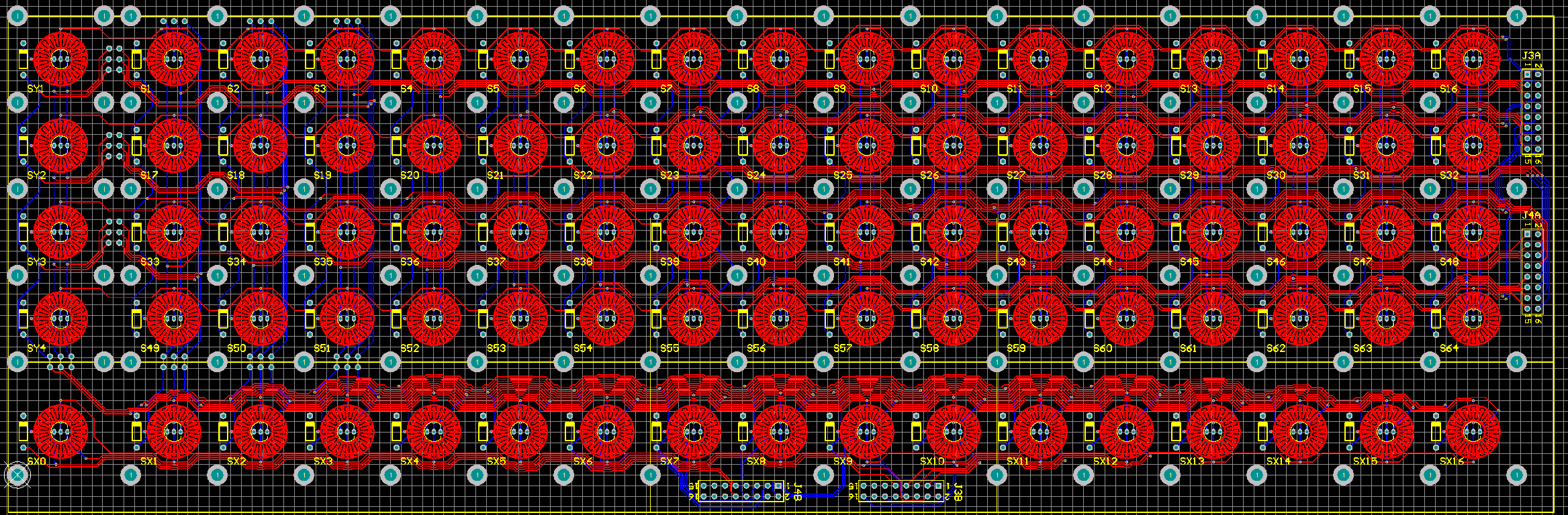
I've done the layout according to the schematic... the row of extra buttons at the bottom was pretty tricky, but I guess I complicated it by putting ludicrous amounts of mount holes (much like my MB-SEQ PCB) to give full flexibility in construction, i.e. mounted above to aluminium front panel, mounted below to base like sammichSID, plenty of holes for mounting a "spacer" like the Livid ones, or securing the rubber pads separately to the mounts, etc. So as I see it, the most optimal solution is one PCB with 4x16 buttons + 4 on the left (i.e. just like the schematic). That layout also supports the extra 1x16 row + shift button, as either a separate PCB or as part of a 4x16 PCB. So in theory, if this went to a mini bulk order stage, you could structure it as two different PCBs, either with the extra 1x16 row attached or separate. I chose this arrangement over the 8x8 because it simplifies the "scalar"-ness of the design... I couldn't find a nice way of making an 8x8 board stack vertically and horizontally without creating four different 8x8 layouts, each with different placements of the J3/J4 connectors, and then there would still be the extra 1x16 row to deal with. Also, the aim was implementing BLM16x16, not make a monome clone... which is easily done with the breakout boards already available by Livid (but not with bicolor LEDs though). I'm also recalling discussions with TK regarding this: However, this 4x16 PCB should work as an original BLM 4x16 extension to MB-SEQ, a much more useful "reuse" than trying to be all things to everybody. Would the original BLM 4x16 extension to MB-SEQ benefit from the extra row of buttons at the bottom? Or would people prefer just the 4x16 plus extra 4 buttons (aka. Track Group select)? If the latter is true, then maybe it is worth putting another J3/J4 connector on the left so you could connect another BLM scalar driver board for the extra buttons.
-
I'm OK with it, although I would like to know who buys it so they can continue to get support from me.
-
I haven't found SPDT switches like you describe, and I've looked very hard. They must exist, because some controllers like the Axis-64 use them, I think. "Piano" type keyboards that have velocity sensitivity typically use two discrete switches... sometimes this is as simple as two rubber membrane switches that will close at different times of the keystroke, with different length actuators above it which are connected to the key. The Axis-49 uses an interesting method of a rubber membrane with two conductive rings at different heights: http://a2.vox.com/6a00cd972aa36b4cd5011015f5dc82860b-pi http://musicscienceguy.vox.com/library/post/the-axis-49-reveled.html I'm using a very time-consuming method to add extra contacts to Cherry MX keyswitches:
-
No, are you referring to the audio socket above the LED?
-
Looks good, I like the yellow. If you are missing a switch, I will send you a one, or get nILS to send you one. Just email me your postal address.
-
Speak for yourself, I can't get any work done with all the noise.
-
That's the LED I was looking at. There is another one: http://cgi.ebay.com.au/ws/eBayISAPI.dll?ViewItem&item=280516196821 but I don't know the brightness. BTW Don't forget to add the price of switch caps for the E-switch tactile switches, which are only available from Digikey AFAIK (part 401-1152-ND), another 48.12 USD for 289. This is why I stopped working on a design using E-switch, it's still a lot to pay for switches/caps and they wouldn't be illuminated. TK's DIY approach is better if you want to make it cheaply, and have illuminated buttons. The Livid pads aren't ideal, they're quite tall compared to the ones used on monome, making the overall height of the box at least 45mm, but the 0.8125" spacing keeps things smaller than the Sparkfun button pads, which means saving a bit on PCBs, panels, etc. It's still going to cost a lot just to make one set of prototype PCBs, but in a mini bulk order (20 orders) it should work out at under 100 USD for all the PCBs required, including driver boards... I'm guessing though... my mini bulk order of SEQ PCBs came to 32 AUD each, and this is over four times the board area.... but with a design using 3 pcs 16x4+4, 1 pcs 16x4+4+16, 5 pcs driver boards, that might bring the board cost down.
-
I was already planning to use 3mm LEDs. It also would require some slight twisting of the leads so the lead spacing is smaller, 3mm bicolor LEDs typically have 0.1" spacing, meaning the outer leads are 0.2" apart, plus width of leads, this is too close to the inner edge of the conductive rubber ring. My current LED footprint has 0.0625" spacing, so outer leads are 0.125" apart. Pads are 36mil x 56mil round. No conflict with plated contacts on PCB which has inner diameter of 0.2" (same as conductive rubber ring on the button pad). While I haven't proved this yet, I think you would need some ultrabright waterclear bicolor 3mm LEDs, like found on eBay... and not the weak diffused kind like you find at Mouser (and what I used on my MB-SEQ). SMD LEDs might work but it's too hard to find them with good brightness and low cost, plus they might not illuminate the cap as well as a 3mm LED which is more in the middle of the hole. 3mm LEDs are cheap and available from many suppliers so that's good. It's bad enough to lock into one design/supplier of the rubber button pads. Even with 3mm LEDs, I still needed to do some tricks with the layout... like taking off the top layer pads, because 3mm bicolor LEDs are typically not soldered so close to the PCB, as the leads are so close together and have stupid right angle bends in them, the outer leads would touch a top layer pad around the middle lead. But when you think of the history of 3mm LEDs, they came from a time when single layer PCBs with wire jumpers everywhere were the norm... :wink:
-
I didn't like any of the bezels and LED holders available at the time of designing the back panel, and I wanted the LED to look the same as the LEDs on the top panel, i.e. just poking through a hole in the panel. So I just made the hole 3mm diameter and glued the LED from the back using superglue. In case it's not obvious, header J2 (next to power switch) is where you connect the LED directly, resistor R81 does the current limiting.
-
BTW don't get confused by the 0.813" spacing dimension in the 8x8 button layout: http://www.lividinstruments.com/media/64griddimensions.jpg Everywhere else in the Livid documentation, it's defined as 0.8125" I'm going to do a layout just for fun... matrix layouts are pretty easy and lots of copypasta anyway. Don't count on me to finish before anyone else or do bulk orders next week etc. :tongue: After layout of the button contact footprints, using a rough sketch of a circular contact, there seems to be enough room to route it all with two layers, it's a little bit easier since there's not so many through-hole pads getting in the way of the bottom layer tracks. The only thing I'm worried about now is whether the wider spacing of the bicolor LEDs would mean the outer pads might make contact with the conductive rubber of the button. e.g. look at this: Does that dotted ring area around the LED represent the inner hole and the conductive rubber is outside that? If so, maybe even 5mm LEDs would fit in the hole. It looks like phunk used double the normal gap between button caps (0.250") so spacing between centers of the first row/column of buttons and centers of the extra left/bottom buttons is 0.8125" + 0.250" = 1.0625" I'll use that for now (unless phunk wants to correct me? :wink:)
-
MB-6582 Starts up, sits on "READY." and does not much else...
Wilba replied to R64's topic in Testing/Troubleshooting
Possibly your C64 PSU is unable to supply enough current to all the SIDs plus the LCD. I wouldn't call this a common problem, but I know of it happening with a few people. Essentially each SID will draw 100mA on the 5V supply. How many SIDs did you insert before you observe the 5V drop?