Wilba
-
Posts
3,310 -
Joined
-
Last visited
-
Days Won
2
Content Type
Profiles
Forums
Blogs
Gallery
Everything posted by Wilba
-
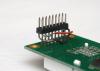
It's the same, that's why I linked to that PDF from here. For extra clarity, J15 is identical in position and pinout to the standard Core, so you can refer to the Core module schematic diagram here.
-
MB-6582 Front Panel from Schaeffer / FPE with minor defects - Poll
Wilba replied to Smithy's topic in MIDIbox SID
If you're not happy with it, then complain. Or rather, tell Schaeffer that you don't think it's up to the same quality that you've seen produced before, by Schaeffer and Front Panel Express. Surely they've made this panel before many times. From my experience, when I wasn't happy with the first set of MB-6582 panels that FPE made (engraving much thicker than expected), I told them, sent photos, they said they'd replace them, I changed the engraving width and sent new files. I can't see why Schaeffer wouldn't do the same - they must value their reputation in DIY forums more than a hundred Euro. -
I found a better diagram: (quote from http://personalpages.tds.net/~rcarlsen/cbm/pinouts.txt) The power connector pinout for the C64 is shown facing the right side of the computer: 9VAC -----7 6----- 9VAC ground -----3 1----- ground +5VDC -----5 4----- +5VDC or no connection 2----- ground Note: although only four pins are actually used, the power connector is a 7 pin DIN, as shown. [/code] Although note pins 1 and 3 aren't actually used by the socket on the PCB.
-
The quickest way for me to show you is to link to the MIDIbox SID "C64 PSU Optimized" diagram: http://www.ucapps.de/mbhp/mbhp_8xsid_c64_psu_optimized.pdf It shows a picture of the plug (not socket) from the front. In case this is not obvious, the two pins on either side of the DIN plug "notch" are the 9V AC pins. It doesn't matter which way these two are connected. Ground is the pin in the middle, 4th from either end, opposite the DIN plug "notch". In C64 PSUs, the 5V can be the 3rd pin from either end, i.e. next to ground. It doesn't matter which side, MB-6582 PCB revision 2 PCBs can handle 5V on either pin. (The revision 1 PCBs don't handle 5V on either pin, you need a bridge to fix that, see here: http://midibox.org/forums/index.php?showtopic=9086 ) Check the voltages with a multimeter before connecting - there's no guarantee the random internet info is correct ;)
-
You can has redemption. That one would be perfect for sammichSID, even when using 6581 SIDs, which require regulated 12V tip positive. However, regulated is better for 6582/8580 also... input voltage will be constant and just enough, keeping heatsink temperature dissipation to a minimum. If you buy it and test it, then I can recommend it and you can haz moar redemption. Or a free frogurt!
-
MBHP_ETH, MBHP_SDCARD, SSM2044, SSM2164 PCB Bulk Order
Wilba replied to seppoman's topic in Bulk Orders
I don't even know why I would need even 1 ETH ever... ;) Congratulations on 1000 posts! -
sammichSID #001 (Arctic Ice remix)
-
From the album: Wilba
© © 2010 Jason Williams
-
From the album: Wilba
© © 2010 Jason Williams
-
Extra SID boards: MIDIbox SID is arranged as one Core8 module (PIC) for one or two SID modules. sammichSID is just one Core8 module and one "stereo" SID module, integrated onto one PCB, with connections to a separate control surface PCB which contains DIN and DOUT modules for switches, encoder and LEDs. So extra SIDs is only possible by connecting the sammichSID base to another Core8/SID module. (In theory, you could also connect to another sammichSID base PCB). So technically it's possible, but you would have to design a new case to fit it all in... and then also deal with there not being any SID 1, SID 2, etc. buttons on the control surface, so no (nice) way of controlling the other SID engines. Similarly, anything you can do with a MIDIbox SID (like connect to an AOUT_NG module i.e. CV outputs to filters, connect to analog inputs i.e. joysticks, pots) is possible, all the ports are there to do it, but you'd have to work out how to enclose it all. It's obviously not designed for extra stuff added inside the case. To answer your last question, it would be easier to get an MB-6582 base PCB and use that as a base for something more custom, or to have more SID modules. MB-6582 contains four Core8/stereo SID modules on it, but you don't have to use them all, and is certainly a lot easier to scale that down than scale sammichSID base PCB up.
-
All the switchmode power supplies I've tried put noise on the audio outputs. They are not recommended (as I've stated in the build guide).
-
MIDIbox of the Week: Station MIDI controller by Ander
Wilba replied to TK.'s topic in MIDIbox of the Week
PCA9635 looks like an interesting chip... certainly a lot easier than doing PWM in firmware. -
UPDATE: I am currently packing batches #9/#10. This was supposed to be May's batches (50 kits) but it has dragged on into June. I'm still waiting on case parts. The matte black acrylic I use for cases is now out of stock, so I don't know when it will be back in stock. This might delay batches #11/#12 even more. Similarly, the Displaytech brand yellow-green LCDs I normally buy are out of stock. I've substituted some Winstar LCDs for this batch, and I will continue to use them in future, as they look a little better (black bezel, slightly better contrast). Due to cancellations, people not ordering kits with SIDs, etc. I didn't run out of SIDs when I expected, so I still have a few left for some lucky people in batches #11/#12. I need to work out how many more kits I'm making in the next two months so I can order more PCBs and not be overstocked. There's currently 104 orders on the waiting list, but how many of these will become confirmed orders, I don't know, especially since I won't have SIDs for most of them. I'm sure there are lots of people who won't want a kit if they can't get SIDs. So it seems likely that I will do 100 more kits which will cover everyone on the waiting list now, and then stop this continual production. I can make more in future, but the waiting list will have to get up to at least 50 kits.
-
MIDIbox of the Week: Station MIDI controller by Ander
Wilba replied to TK.'s topic in MIDIbox of the Week
Thanks Ander for the diagram... it is definitely something I am interested in trying... It might be possible to use Ponoko to laser cut 3mm acrylic and glue two pieces together to make parts with notches. I hope eventually you will show us what is on the PCB, and how they are all connected. It looks like you made a multipurpose PCB that can be either a Core32 or some kind of integrated DIN/DOUT/control surface. This should be MIDIbox of the Year :thumbsup: -
MIDIbox of the Week: Station MIDI controller by Ander
Wilba replied to TK.'s topic in MIDIbox of the Week
INSANE... :drool: I love it. Please share your secret of how the switch "cap" works! You're pressing a fairly large translucent rectangle. What is it made of? How is it supported? Maybe something like this would be a great alternative construction for the BLM and other MIDIbox control surfaces. -
grounding question r/ tactile switches and LEDs
Wilba replied to cantgetnosleep's topic in MIDIbox HUIs
You can tie all the LEDs and switches to a common ground plane. You don't need heavy-gauge wire between the boards, one wire of a ribbon cable is enough. Since 16 (or 8) matches the number of inputs/outputs of DIN/DOUT modules, you might want to consider putting the shift registers on the same board as the switches/LEDs... then you'll only need 6 wires to connect these boards to a Core (or together)... otherwise you'll need to connect 32 wires (+ground) between these PCBs and DIN/DOUT modules. It's not much extra routing. This only works if you have enough room for the ICs, resistors and resistor networks. -
Pulling out R12 was something to possibly fix a problem with the Optrex STEP LCDs (from fussylizard's bulk order). I don't think it has any effect for the fairly standard yellow-green LCDs that nebula was selling. I don't understand how removing R12 would affect LCD contrast, it's only a pullup on one of the signal lines to the LCD. These displays work fine with ultracore, but they're not exactly 1:1, because it's only 14 pins on the header, and the backlight pins are on the other side. So only the bottom 14 pins are 1:1, the B+/B- need to be connected to the backlight pins on the other end of the LCD. On my setup, I have two wires of the ribbon cable extend past the 16pin IDC connector (attached to the LCD) and those wires soldered directly to the backlight pins. Perhaps you're connecting the LCD to the 2nd LCD header on the ultracore, which won't show anything unless it's running an app that uses a 2nd LCD, like MB-SEQ. I think you'd want to configure it to NOT be a router.
-
MBHP_ETH, MBHP_SDCARD, SSM2044, SSM2164 PCB Bulk Order
Wilba replied to seppoman's topic in Bulk Orders
Any Aussies (and Kiwis) needing an ENC28J60 source can piggyback onto my next Mouser/Digikey order. Maybe I should just get all the parts for the MBHP_ETH module in bulk... some of the other parts would be hard to find here. Does anyone already have a BOM for Mouser? -
J8_CORE1/J9_CORE1 in the Core section of MB-6582 base PCB is identical pinout to the J8/J9 header on a Core module. However, it is poorly labelled. Vss is at the end on the right. You will need to remove at least the first 74HC165 and 74HC595 in the DIN/DOUT chain on the MB-6582 base PCB (i.e. U16 and U21) so that there's no conflict with the external DIN/DOUT modules. You will also need to upload something like setup_8580.hex which uses the default DIN/DOUT wiring, as setup_mb6582.hex uses a different DIN/DOUT wiring (i.e. the combined LED/switch matrix). (Sorry that I haven't been following this issue and helping you, I'll jump in after your next report).
-
I will buy the blue knobs if no one wants to buy the lot including the blue knobs. Maybe a buyer would prefer the lot including the red or grey knobs. (I was nicestupid and sold all my spare blue knobs to people over the years since I built the MB-6582 prototype.) BTW to potential buyers, I confirm these are genuine new-old-stock 6582A SIDs from me.
-
1) It could be dead. Some people have successfully salvaged a 6581 from a C64. I am not one of them. Can you observe a spike in the audio output when you turn on the C64? i.e. level meter jumps up to max then returns to nothing? Also, do you hear anything on the audio, like noise, to suggest it's outputting something (i.e. prove your audio input is really working)? 2) C64s that need 12V (for 6581 SIDs) generate 12V internally. AFAIK they add 5V DC to 9V DC and then regulate this 14V through a 12V regulator. 3) It's hard to say what might have killed the 6581 in the C64, if it is dead. You could test the voltages on the SID socket, with or without the SID in it, to check it's getting 12V DC on pin 28, etc. Don't use pliers to remove an IC. The cheapest extraction tool is better than that. http://www.altronics.com.au/index.asp?area=item&id=T2550 I can't really recommend what's best... it's probably unlikely that the C64 will "kill" your other 6581s if you try them, but then again, I also read somewhere that connecting C64s to an amp can sometimes kill the SID, which is why the MIDIbox SID module has an audio buffer to "protect" the SID.
-
I don't know what you mean by "not backlight". Maybe this is what you are looking for: http://character-lcd-lcds.shopeio.com/inventory/details.asp?id=935&cat=Lcds&sub=Character%20Lcd Otherwise, browse here: http://www.crystalfontz.com/
-
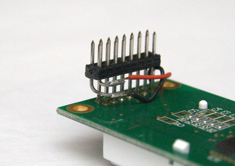
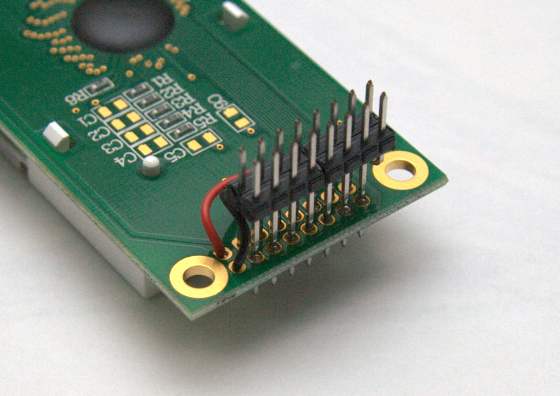
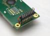
How to connect an Optrex STEP LCD to a sammichSID base PCB ... and just to confirm: pins 3-16 on the display match up with pins 1-14 on the base PCB. Pins 1 and 2 on the display (backlight pins) match up with pins 15 and 16 (B+ and B-) on the base PCB. I'll add this to the build guide someday :wink:
-
The good thing about these Displaytech LCDs is that it uses a single 3mm LED. If it ever dies, you can remove the bezel, cut the LED leads and desolder the remainder of them in the pads, twist the LED to break the glue holding it into the clear acrylic diffuser, then replace with another 3mm white LED. Replacing the bezel can be tricky, you need to get correct alignment between the LCD and the PCB via some conductive rubber things. If it's wrong, you get garbage on the display. I just thought I'd mention it for future reference... some people would just replace the whole LCD, but personally I like to fix things when it's possible.
-
Daß ist eine gute Nachricht. Viel Spaß!