

Wilba
-
Posts
3,310 -
Joined
-
Last visited
-
Days Won
2
Content Type
Profiles
Forums
Blogs
Gallery
Everything posted by Wilba
-
BAD NEWS :sad: I have run out of the "true-green" low-power LCDs, and only have a few amber low-power LCDs left. I can't get more for a reasonable price, so I am switching to stocking only the common yellow-green high-power LCDs, which I can buy on demand from anywhere, for a good price. I still have plenty of the white-on-dark-blue LCDs.
-
He also didn't reply to the invite into sammichSID batch #1 or #2... but neither did Echopraxia so I thought it was just typical American arrogance... :D ringmod45 might have a contact number... I combined shipped stuff to them, and ringmod45 might have arranged to pick it up.
-
There are no traces to GND because there is a ground plane. It's the middle pin of J1. I'm curious to know why you are "splicing" a new plug onto the C64... also, there's no such thing as a "12V" and "9V" C64 PSUs, they all have the same output (9V AC + 5V regulated DC), although they can have different power ratings and sometimes the 5V is on a different pin (hence the bridge you seen between two pins, to allow 5V to be supplied on either of those pins).
-
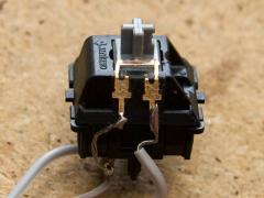
From the album: Wilba
Made with two pins of a female header and a cut sliver from the gold plated disc inside a 12x12mm tactile switch.© © 2009 Jason Williams
-
Blue LEDs are evil! They will burn your retinae! Having said that... your sammichSID looks really cool! Congratulations!
-
Don't use MIOS Studio for uploading patches, use the patch editor.
-
I guess that means problem solved?
-
Thanks for the glowing review (and the lol for the gloves)!
-
That reminds me of the problem I just had with Windows 7 and my M-Audio Delta 1010LT... it was echoing MIDI In to MIDI Out. On startup, a MIDIbox will output an "upload request" on MIDI Out. F0 00 00 7E 40 00 01 F7 If you only had the bootstrap loader, you get this sent every 2 seconds. If you have MIOS installed, you only get this once. Start with disconnecting sammichSID's MIDI In to your PC's MIDI Out. Only have sammichSID's MIDI Out connected to your PC's MIDI In. Check you have your MIDI Routing correctly configured (like the build guide shows). Open up both MIDI In and MIDI Out windows in MIOS Studio. Power on sammichSID. Do you get the upload request? If it is appearing in both windows, then that's not sammichSID at fault, that's your MIOS Studio/MIDI setup echoing MIDI In to MIDI Out. I'm assuming you got to the point of having the "READY." showing on the LCD. If so: Disconnect sammichSID MIDI Out to your PIC's MIDI In. Only have sammichSID's MIDI In connected to your PC's MIDI Out. Open the LCD Debug window and send some LCD commands. This SHOULD work if the sammichSID's MIDI In is working. You will see the command being sent in the MIDI Out window and SHOULD NOT see it in the MIDI In window. Run these tests first and report your results... then we can work out where the problem is (MIDI interface, MIOS Studio setup, sammichSID hardware, etc). Also report back with your PC setup (OS, MIDI interface, etc.)
-
[S] unbuilt Stribe Kit, 8 strips, red LEDs !!NEW IN UNOPENED BOX!!
Wilba replied to Wilba's topic in Fleamarket
*BUMP* I didn't get any offers, and it's time to stop hoarding stuff I'll never get around to building. Somebody please make me an offer, or I'll be forced to give it away to some gottverdammt Klugscheißer who doesn't deserve it just to make room in my cramped little study (aka. the sammichSID factory). -
After the forum switch, I noticed that birthdates were visible all the time (I didn't think they were in the old forum), and I made a comment to Twin-x, who probably set them all to 1/1/1. Which is why everyone's 2009 years old today, except me (I turn 100).
-
I like it when problems just go away... :)
-
MB-6582: 4 synth engines, 8 SIDs, 15 knobs, lots of LEDs, lots of hunting for parts, medium newbie-friendly, expensive. sammichSID: 1 synth engine, 2 SIDs, 1 knob, some LEDs, no hunting for parts, high newbie-friendly, cheap (compared to MB-6582, SidStation, HardSID). modular MIDIbox SID: whatever you want... 1-4 synth engines, 1-8 SIDs, low newbie-friendly, variable cost (but still always cheaper than SidStation, HardSID).
-
:whistle: Cool for both of us (I am not in the mood for troubleshooting, I am still recovering from a hard drive crash, not the boot drive but almost as bad...)
-
Congratulations! So did the "no power" problem go away or you found what was wrong?
-
Maybe you had a bad solder joint for the power socket or switch, and mounting the rear panel moved it. Or you didn't cut the leads on the bottom short enough, causing the bottom panel to push them into touching, or something like that. Take the base PCB out of the case and take out the ICs including SIDs. Check the bottom of the PCB for any shorts or leads that are too long and now touching. Then with power connected and switch turned on, check what the voltage is at J1 and on the 7809 between the pins marked with orange and green dots. It should be around 12V or the same as your input DC voltage. You need to actually do some tests and prove what is connected that should be connected, and what might be shorting with something else. Check that none of your power rails (i.e. 12V, 9V, 5V, Gnd) are shorting with each other. Report every test you did. I can't help if you just ask vague questions like "why isn't it working?".
-
The LCD was tested before I packed it, so it should work. Do you see the LCD backlight when it's connected? Was the contrast pot fully counterclockwise? Most likely you have one pin that isn't soldered properly. Probably the ground pin, 5V pin or the contrast pin. Test there are no shorts between adjacent pins on the LCD header. Test there is continuity between pins on the LCD and matching pins on the bottom of the PCB. You will need to assemble the PCBs without a case.
-
Sammich SID problem: RN1 & RN3 soldered in oposite way
Wilba replied to maniac's topic in MIDIbox SID
You need a 6-pin 10K resistor network... i.e. it has 5 10K resistors connected to a common pin. Mouser Part 264-10K-RC http://www.mouser.com/catalog/specsheets/XC-600048.pdf It is type A (common) not type B (isolated). -
Batch #3 will ship tomorrow-ish.
-
Sammich SID problem: RN1 & RN3 soldered in oposite way
Wilba replied to maniac's topic in MIDIbox SID
Unfortunately there is no way you can fix this in software. The only solution is desoldering them. The safest way to desolder them is to cut them with wire cutters so each pin is separate, and then desolder each pin one at a time. I would do this one pin at a time, i.e. cut, desolder, cut, desolder... so when you cut it, it's just one pin at the end with room to move. If you cannot find these resistor networks locally, I can post you some more. Just email me with a postal address. -
1. Sync LED isn't being used for anything. 2. This can happen when using ultrabright LEDs... it's an artifact of them being in a matrix. I noticed the same effect, it's most noticeable in the 8x8 mod matrix LEDs, where a single LED would have a "ghost" in an adjacent column and in the same row. My guess is that as each column gets scanned, there is still some lingering current sinking on the previous column, I don't know exactly why, it doesn't seem to affect the switches, i.e. there is never any false triggering of switches which are also connected to the same matrix. The only solution is to reduce the brightness by increasing the resistors, however, this can also lead to the other effect you notice, if you're running ultrabright LEDs with such low current, then this will highlight any variation in brightness... and also (I have to admit), cheap ultrabright LEDs from China are made for people pimping their cars and not really for control surfaces. 3. This sounds like your C64 PSU cannot deliver enough current on the 5V supply when using 8 SIDs, each SID draws 100mA on the 5V supply. I've posted solutions in other threads... either replace the C64 PSU or reduce current on the 5V supply by switching the LCD backlight to use 9V supply. The best test to see what the problem is would be to measure current load. The easiest short-term fix is disconnect the LCD backlight (perhaps desolder the A/K wires on the LCD - they are nearly always pin 15/16) and then see what happens, you'll probably have it booting nicely with 8 SIDs and working fine, then you'll know the problem is purely the current load being too much for your C64 PSU, you can then try the alternate backlight supply idea, cut one track, add a wire, should be fairly easy... I recommend replacing the brightness trimpot with 50K for more control of actual current supplied to the backlight, and also learning how to measure current being supplied to the 5V rails AND also measure current supplied to the LCD backlight (after you do the voltage fix). I will have to write up how to do this one day, a lot of people have this problem and it seems like I'm explaining a solution too often!
-
Yeah I'm packing sammichSID kits in between the usual Christmas stuff.
-
Awesome paint job and nice mods... Tell me about the paint... that is so much better than the stuff I use, I love that gloss.
-
I just received some extra top panels so I will be trying something other than acrylic paint using a brush... maybe these markers will work better.
-
Looking For Someone To Complete Last Stages of My MB-6582
Wilba replied to toneburst's topic in MIDIbox SID
Yeah good idea... send to nILS for fixing... he solders like a drunken monkey, but he gets the job done. :thumbsup: