
tashikoma
-
Posts
183 -
Joined
-
Last visited
-
Days Won
5
Content Type
Profiles
Forums
Blogs
Gallery
Everything posted by tashikoma
-
Do you know this one?: Misa Digital NSC-32
-
the package i had is aprox 24.5mm long...
- 13 replies
-
- 1
-

-
- line driver
- cv
- (and 1 more)
-
thanks Andy but i just use infos of the forum! (when i success to find them) great idea your building tip be carrefull of the package: UDN have extra millimeter in front and rear so i use extra sockets on half sockets to fit them! you need one pin space between each UDN it can't be equal to doutx4 or not in the same line..... exemple in simple form cause i can't explain in english: for four UDN (a - is one UDN): ---- not good - - - - good -_-_ good
-
ACHTUNG!!! ATTENTION!!! WARNING!!! Latigid on raised a bad point: UDN have no protections on outputs! not good if output is shorted to ground (as this happens every time you plug into a socket). so: 1k resistors after each UDN outputs do the job!
-
Hi oozitron Yes it works well with +/-15V
-
ok for me you've got one mdi IO board. change the optocoupler..... verify your midi signal path for short... exchange the ribbon cable... between core and J1 you could try monitoring your midi port with a external midi interface and midi cable in mios studio... you could test with midi IO 4 or midi IO 1
-
Hi jbdiver i think you're talking about the separate dedicated zone for BLM on the quad IIc from smash TV? this zone was designed for J11 on the old core STM32F1 who support this purpose NOT stm32F4! as you see it's not direct pinning compatible with the stm32F4 and not direct compatible with J2 midi IO! it make bugging ours heads! no problem you have to adapt! use regular crimp connector on J2 and the other side of the cable solder directly on the BLM zone the 4 used pins (mi1 mo1 vss vdd) isolate unused pin cable. it make a special cable between MI1 /MI2 from BLM zone to J2 MI3/MO3 to use midi in/out 3 from the midi IO chain... ( if your setup is only 1 midi IO board). if you have two midi IO board in your setup , you have to reserve one midi in and one midi out (exemple: midi IO4 on your midi IO chain) and don't stuff the components on the quad IIc BLM zone (the required midi components are already stuffed in the midi IO board) but wire directly midi sockets to the BLM conbined midi socket. .
-
32 bit core...AWESOME!
-
Hi Drew, (with pleasure! this is not my idea, it comes from somewhere in the forum ! don't remember) YES DOUT pins to UDN pins are connected without 220R resistors. if you have just 5v trigger drum module you could drive it directly from DOUT without the 220R and without UDN! UDN is a deluxe solution and protect 74hc595 outputs. a trig signal is little draw but with UDN outputs are stronger : you could drive a solenoid! (but not the big ones!) Have a good end of year! Nico
-
Which encoders should I buy for SEQ V4 build?
tashikoma replied to fundamental's topic in Parts Questions
Yes i see that info on your great topic (seq construction) i will change the BOURNS for the ALPS after christmas... it's not acceptable ALPS need pin bending they doesn't really fit... but i love the feeling.... Bourns fit perfectly and and are recommended in Wilba CS / MB 6582 pages.... it's surprising that it's works with different pinout the logic will be to invert two pin and use detented 3... don't know if i will go like you or like the logic! my first seq was not Wilba cs but perfboard so i use it in "normal" pinning but the Bourns in non detented are great for MB-SID. they're was an old tip for yamaha sampler Ax000 to have condensator A-pin to ground and another condensator B-pin to ground..... seems to force the pulse of tired encoders -
Good news it's a rainy day! so recidivism to crazy experimentation on the meanwell with IIC midi and line driver transmitter the SEQ draw 300mA , line driver seems to stabilise the PSU load! with IIC midi ,ethernet module and line driver transmitter, the SEQ draw 410mA ... when line driver transmitter is in communication the current rise at 600mA (i don't test with ethernet communication but seems to be +100mA) the CS is now stable! the PSU works perfectly!!!! also stable with the LC-filter. (who previously force to bug) on the meanwell datasheet this PSU seems to be capable from 0 to 3A no load requirement! but reality says more than 300mA to work! i keep the meanwell in the case, the SEQ is now BLM powering ready youpi! morality : at 10e it's a good value if more 300 mA load is respected thanks Peter ,Altitude & Andy!
-
PERFECT!
-
Which encoders should I buy for SEQ V4 build?
tashikoma replied to fundamental's topic in Parts Questions
Hi, i take the bourns pec16-4220f-N0024 for my last seq and they loose or pass some steps (approximatly each 10 step)....there are not precise! don't like the feeling too... got the same model on the datawheel with switch it's the same... my first seq is equiped with alps stec12 from reichelt and there are great... precise and good feeling , you feel each step...but look cheap construction! don't have experience with alpha's -
Hi Thorsten Yes V/oct is properly selected i tried also with other modes. the bug only affect the voltage range of channel 1 and 2 all others are goods approximately (calibration can't really be done): middle =2.5v max =4.05v 1v= 0.26V 2V=0.55V 4V=1.20V 8V= 3.2V Approximately same range value for channel 1 and 2 changed the max and tl074, same. resistors are in good place ...trimmers are from the same batch... less than 10cm core to line driver transmitter, less than 10cm receiver to AOUT Next test will be AOUT directly connected to the core. and voltage test of real high note. but it's not really a problem i could use this two channel for filters , 6 goods CV are available , it's perfect for my config! now everybody is using AOUT NG...
-
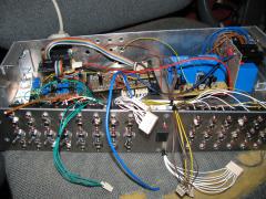
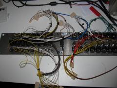
Hi Midiboxers, Line driver breakout CV /gates finished i used AOUT and a tweeked DOUTx4 and of course the line driver receiver! DOUTx4 is stuffed with regular 220 ohm resistors for leds indicators and UDN2981 for gate booster. UDN 2981 are directly linked at the outputs of 74hc595 (before the 220ohm resistors) . the gates assigned to CV have two UDN 2981 (input in parallel) one is powered by 5V (eurorack 5V gates) and go to minijacks and the second is powered by 12V and go to 1/4jacks (oldschool 12V modular gates) same for the extra drum triggers gates: 8 are in 12V and the last 8 are in 5V... need 1k resistor at each outputs of UDN for ground short protection !!!! 3 PSU inside: 12V for 12V gates, 5V one for the 5V gates /line driver receiver/DOUT/AOUT and bipolar 12V for AOUT. the 5V line from the seq is cut on the receiver. i could have used the same 12V from bipolar but a dedicated 12v make sense cause wanted the AOUT "stability" as usual i've got a bug : the CV 1 and 2 have the same problem: at calibration voltage are divided by 2... don't know why...not the ICs , no shorts, ( problem on the 2 first channel!) all other 6 channel working properly. the calibration "max" voltage is 4V on this two channel is it possible to be a log error? i build AOUT because i've got max525 in stock... is someone use this config and could confirm that line driver work with AOUT?
- 13 replies
-
- 1
-
-
- line driver
- cv
- (and 1 more)
-
Line Driver CV AOUT rack
-
-
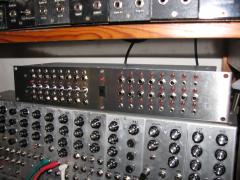
From the album: AOUT break out
-
Hi all, We could multiply the clocks in the CV configuration page but not divide them... It could be a nice feature to have a divider ratio parameter... that 1ppqn could be dividing... Like the MBCV V1 there's no possibility to have long divided clocks ( i use clock divider Yusynth module from modular to perform that!).
-
 tests ok!
 -
From the album: AOUT break out
-
From the album: AOUT break out
-
i've done the test last month it works...
-
Yeah! congratulation Jbdiver!
-
Yeah Andrew! TRACOPOWER with symetrical 12V is good for CV outputs.... after do more tests ( was busy this week) I found that the random noise in the video is from an ethernet powerline device . not from the supply or seq! (mesured at 50mV (100mV P-P)) 10 cm between core and PSU. internal ripple of the seq is consequent with the meanwell! 30mV (60mV P-P) Peter your filter rocks! attenuation of 30mV ripple to 5mV (10 mV P-P) and good sleekage. with the scope and filter it's ok! but without the scope and with the filter the CS crash immediatly after power on! i see the real benefit of the filter and hazard made the filter permit me to "force" bug! (extra cap of 2200uF will act as reserve of power) the seq current is 270 mA , without (for the moment) the IIC and midi indicator external leds. i test with USB powa' or classic transfomer/7805 and lab PSU and the seq is stable.... The crash is caused by low load of switching PSU , the PSU go to "idle" mode! (5.050v to 4.930v)... Have to do tests with more load on the PSU... perhaps a regulator or UBEC to load the switching PSU would do the trick! Or SEQ with extra external ledstripes! The simplest way is to go with classic design PSU and leave the idea of powering BLM from SEQ... from this switching PSU. a supply for BLM another one for SEQ and one for the line driver CV rack! there will be for everyone also it's a bad idea to have long extension of power rail with high current low voltage...
- 11 replies
-
- 1
-
-
- blm
- power supply
- (and 2 more)
-
THANKS! the bug is still present (it's a rainy day) done more test: video the switching frequency is not constant and there some random noise... crappy new unit?