tashikoma
-
Posts
183 -
Joined
-
Last visited
-
Days Won
5
Content Type
Profiles
Forums
Blogs
Gallery
Everything posted by tashikoma
-
OK!!!!! thanks Janis :thumbsup: Regards
-
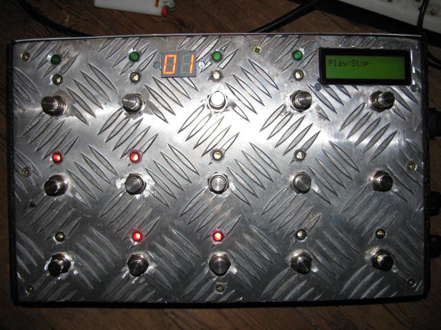
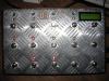
THX Durisian so after building the "mini" pedalbox i was thinking building a more complex and versatile solution.... the front is a piece of 1cm aluminium previously it seems to be a walk up for truck but my friend use it to be a below of hot dish! after a good meal my friend offer me the frontpanel... i drilled and cut the frontpanel switch are momentary from BANZAI music,dpdt relay from futurlec other component from reichelt (reichelt have now 20e limitation for export ,i'm french) the core was an old core from my stock rearpanel is 1,5mm aluminium drilled by myself the rest of the box is 5mm plywood 1 transformer for pbx 1 transformer internal power supply for external stompbox a lot of brainstorming :logik: problem was the digits i had in stock 2 digit common anode the good way is common cathode! (it was the first time that i use digits) another problem with the bankstick .... you've got to program the bankstick before load the application (i'm not sure of the method i don't remember!!!!!! :frantics: ) i build 2 midibox sid ,1 MB64 ,1 MBCV ,1 MBseq, 1MiniPedalBox I am a bit stupid but its starting to enter in my head :sorcerer: PBX software is a long-scheduled!!! but after all value edited it's cool!!!! :thumbsup: i'm a bit confused between rig and gig.... it works good :whistle: THX to TK and you :w00t:
-
wow... :)
-
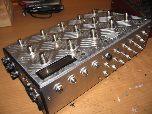
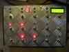
pedal board V2 4 foot pedals + 4 internal pots 4 relay loops (bypass + bypass + parallel + a/b box) internal power supply for fx pedals 15 switchs (8 banked 5 fixed) again: thanks to Durisian!!!! :D
-
 :thumbsup:
 -
i've purchased the same lcd the backlight was mirrored not the datasheet :twitch:
-
HI I've purchased a red on black LCD 20x4 rt204-1 (version 2) Anode and Kathode of backlight are mirrored (not on the datasheet) so i've got the backlight ok now in 4bit mode no letter just two line (line 1 and line 3) it seems like freezed :whistle: the application works great in background...... after a test on the second core J15 ; the display tell me MIOS version and the ID number so it's not the lcd so i've test the main core on the second slave socket and the lcd work with mb sid application...... i've redo all solder points and they are good.... no LCD :pinch: so with the multimeter I've test all the LCD points to core R/W was shorted to ground ....the solder was good . i think this is a bad pad thanks to the cutter! now it works.... :sorcerer: when i press the sync button the LCD switch to bpm menu but the dedicated led doesn't illuminate. is it normal? :whistle:
-
 magnifique!!!!! It's look very very clean!
 -
thanks peter!!!!! i can not wait you to see your frontpanel!!!!! :tongue: i love your double square leds design... :thumbsup: looking to the BLM connector schematic: MI2 MO2 are spare? they are direct connection but with all option (ethernet ,CV&gates , din syncro and din start) there no spares available? sorry there are on J11 :whistle:
-
thanks Thorsten!! :sorcerer: (nice to have a comment from the genius god of uccaps! :thumbsup: ) I've understand now the song mode it's exactly what i was searching! how to assign mixer map! yeah!!!
-
Merci Julien! after use the seq ... it's a very good machine lot of possibilities lot of good fonctions.... great the only thing that i don't understand is the mixer section in event you can choose the port and the channel but not program change i don't understand how to assign program change per track. is it possible?
-
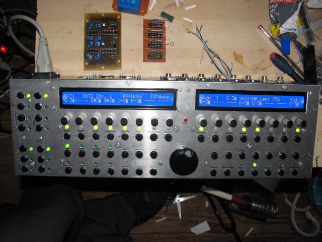
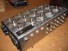
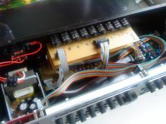
thanks!!! :rolleyes: there's just enough place for all the boards!!!!! there two transformer : 2x9v(2x2A) and 2x15v(2x100mA). DOUT , standard LEDs and DIN are powered by another 7805 because the 7805 from the core was too hot!!!! the second 5V power could drive a BLM with low current leds!!!! rear panel is metal from the back of an old cd player.... the rest of the box is plywood!!!! it's time learning use it!!!!! :thumbsup:
-
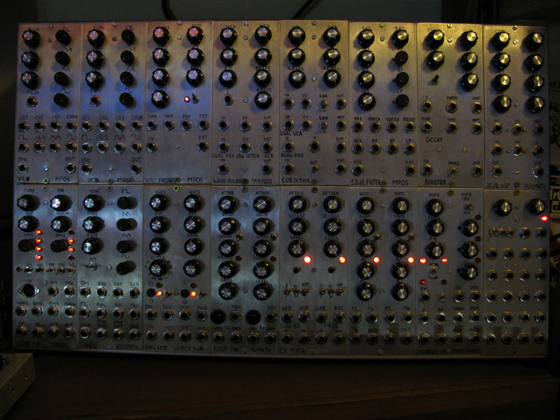
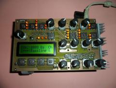
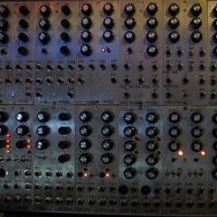
thanks to TK and the community handmade aluminium frontpanel with standard cheap drill!!!! not perfect but works DIN and DOUT with a lot of wiring , duo GP leds ... lot of work !!! the Wilba CS is a better solution! seq V4 is amazing.... whaouh!!!!! next step is installation of the aout and the four midi IIC options......
-
AMAZING work , GREAT topic :thumbsup:
-
How did Wilba do it? SEQ V4 CS with only 6x74HC165 & 2x74HC595
tashikoma replied to Hawkeye's topic in MIDIbox SEQ
yeah!!!! thanks Peter !!!:D -
How did Wilba do it? SEQ V4 CS with only 6x74HC165 & 2x74HC595
tashikoma replied to Hawkeye's topic in MIDIbox SEQ
Hi MByers i've got all the parts for finish a MBseq :frantics: i was thinking building the WILBA's control surface in DIY mode (veroboard) :whistle: but i realise the WILBA CS is matrix wiring. can i build it with standard DOUT and DIN for all switchs and duo leds? or i need to do the matrix switching? thanks -
thanks Smithy i was thinking that it doesn't play the original event but delaying back it!!! it will be cool to have a feedback fonction (controlled by button or encoder) for repeating more than one time.........!!!!!! (two times three times .....six times....) exactly like audio delays one time to hold.........!!!! so it could be very simple!!! a killing grooving machine to midi looper....... i have no idea to program that!!!!!!! :frantics: if someone can do that i will build it!!!!!
-
thanks qwasq for the test..... :thumbsup: and a very big thanks to durisian for the solution and the new version of pbx editor....... :thumbsup: yeah!!!!!! :w00t: and special thanks to PC PSU!!!!!!! :frantics:
-
hi is it a delay like an analog delay for midi or a function who define one time for one event? thanks
-
so i've got 2 footpedal : one can be plug directly into line 6 so not a real problem for now.......... don't hurry up..... :rolleyes: i've test with midibox 64 apli and the AIN entries are OK...... the 2 footpedal perfectly works....... so this is not the pic!!!!!! perhaps is my H config who sucks ..... cause to few shift register..???????? (just 1 din) there 's not a lot of parameter to config...... this way appears to me easy!!!! i'm sorry to my poor knowledge in programming!!!!!!!! i'can't help us!!!!!! thanks man thanks for the quick replies....... is someone else test it with more than one footpedal? it could be usefull to know that!!!!!!!! :flowers: cheers
-
yes AIN_NUMBER_INPUTS is 4 in pbx_config.h and connected to the first 4 ain inputs (A0-A3) i will try with another pic..................!!!!!! :whistle: Thanks
-
i've check all but but input 1 is the input for all......... is someone use or test with more than one footpedal????????? :sweat: thanks.
-
Thanks durisian tap tempo is ok!!!! full working .....yeah...... i've check and it was a bad midi cable........sorry!!!!!!!! :sorcerer: but for the footpedal no issue........... i will check the h file and retest it........ perhaps i've upload aplication with this bad midi cable!!!!!!! see you soon spacecowboy!!!!!!!!!!!!! :frantics:
-
perhaps find 2 bugs (or perhaps i'm a bug!!!) :) my config is 4 footswitchs and 4 footpedal....... -tap tempo footswitch dosn't transmit to my line 6 delay the tap tempo......... but works inside pedalboard....... - when connecting more than one footpedal all the footpedals control the same parameter and the information on the LCD are the same... so just one footpedal is usuable (i've edited and patch all CC footpedal in the pdx editor) i have no knowledge in programming aplication !!!!!!!!!
-
this is like the Morley style!!! great technique for the piece of plastic use not your credit card but an old fidelity card......... :frantics: there's the Digitech style: sensor fixed inside and the led is fixed to the pedal..... the pedal drive the distance between led and ldr the only problem is with a lot of use , cable of led can broke or desoldier.......need to glue it mechanic style My link My link and a very good 10k potentiometer .... expensive and hard to find this technique is the most expensive and need a perfect adjustement of mechanical....... so the Berhinger Morley style is easiest and cheapiest technique led and ldr need to be in dark closed enclosure