
tashikoma
-
Posts
183 -
Joined
-
Last visited
-
Days Won
5
Content Type
Profiles
Forums
Blogs
Gallery
Everything posted by tashikoma
-
Hi Peter, You're right , i test with a scope and the Meanwell PSU is linear. no ripple. ( the switching frequency interaction problem seems to be a complot theory from my imagination!) today the SEQ is stable (4h running) with the meanwell no CS crash... i don't understand , no change have be made ... i don't know what happens yesterday! (it was a rainy day) yesterday i flip several times between USB and Meanwell PSU and the bug was reccurrent with the Meanwell. (power at J2 withouth the USB power jumper) i will do tests next days and run the SEQ to see if crash reapear... you're "UBEC" regulator from modelism is a great tip, i will give it a try... thanks Best Nico
-
Yeah Andy! your solution is more simple! i am so stupid that i would have never thought!
-
Hi, I power the Seq v4 with USB , Fine , stable (since a month) i want to permute for a permanent dedicated PSU than USB in the seq case (BLM extension ready) so i've bought a meanwell 5V 3A at reichelt . Meanwell PSU this switching PSU made the Control Surface crash! ( i suspect interaction between supply switching frequency and the frequency of the CS matrix also ripple/noise) i could build filters to sleek the PSU but the config is a bit special. (filter have to be well designed for a certain current, BLM is not constent current, and if the CS crash the BLM will do too! don't like this sensible way) so i thinking use classic design PSU with transformer and a linear LT1085-5 regulator (not done yet) i never used this regulator but i will test. Is someone have experience , suggestion or tips with higher current than 7805 regulator. (perhaps another regulator familly than LT1085) Thanks Nico
-
for grounding the 4 unused AINs inputs: take a 10 pin IDC male connector, kill the 5V pin , and solder AINs and grounds pins with a unused component leg, easily removable so it could be evolutive for future...
-
first MIOS bootloader if virgin pic via burner ...and after the .hex file via midi in blm_scalar_v1.0a.zip...
-
Hi Thorsten , thanks for the procedure. it was not the SRIO chain it was the PIC! it's my first totally SMT project and i take care but i think i do crappy job... find more than 20 shorts (between ground and 5v / SRIO/ leds...) fix severals shorts but some are unfixed and certainly unfixable! i know were are the shorts but i couldn't fix it... it's a nightmare! at the several time that i rework and rework and rework the board i damage soldermask... i've killed some pads ..etc Andy pass several time on support with me. (great man!) i don't do honors to his great design. i will restart with a new BLM board but with more drastic building process. i think at each solder need to be controlled via multimeter to check shorts to ground... next builders must do this process! Best Regards, Nico
-
Hi, The great design of BLM 16x16 by Andrew is certainly too microscopic (smd) for a butcher like me! Andrew help me a lot for debugging some shorts. I made a lot of tests but the BLM doesn't work. the core is Ok , search for a Seq (send each second the same message in Mios Studio) but nothing happens when push on silicon pad (no light and no message in Mios Studio) .the core draw about 34mA (lab power supply) i never plug it to a Seq. i test with the minicore and a classic core with default :project.hex BLM_scalar 1.0a , no issue so i would like to check the SRIO chain SC RC SO with an scope but i don't know the procedure! how to check IC and shmitt trigger? Thanks Nico
-
yeah ! with pleasure! (i must have post in tips/trick than parts)
-
-
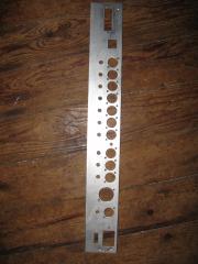 homemade seqV4 backpanel...
 -
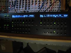
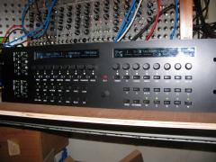 The LCD are cyan.... there were sells as white... (if i was knowing that the schaeffer character colour will be Cyan not white, must be tested before ordering schaeffer!)
 -
-
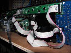 not final ribbon cable!
 -
flash!
-
 The LCD are cyan.... there were sells as white... (if i was knowing that the schaeffer character colour will be Cyan not white, must be tested before ordering schaeffer!)
 -
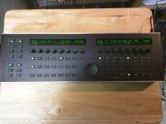 nice!!! love the led button...
 -
for information it fits the BLM case Midi hole: https://www.reichelt.com/Diode-Jacks/DIO-80SN-EMS/3/index.html?&ACTION=3&LA=2&ARTICLE=46282&GROUPID=5182&artnr=DIO-80SN+EMS
-
i finally understand that extra parts of BLM midi socket and the port on smashTV PCB was design for the old core STM32F1... so i will use just only one stage of the MIDI IO for the BLM purpose. (sometimes it's like dumb n' dumber in my head) thanks to all ,thanks for support so
-
2 mA per led if there are all illuminated (that will never arrive in normal use) result 1156 mA so 1,2A (i can't mesure it cause bugged) 1.2A is security value and not the real consumption wich will be less than 1A. i receive the case today , beautifull and look very strong!
-
SD card socktet alternative source? (SD-RSMT-2-MQ)
tashikoma replied to albin's topic in Parts Questions
-
for those who don't find a sd card socket for the core stm32F4. you could use micro SD card and the ADAPTATOR will be the socket like:http://www.ucapps.de/mbhp_sdcard.html first solder unused component legs to the adaptator: solder to the core but leave some space to the board for avoid short (be carefull pinning): you could fix it (glue) if you want (not done for me legs are sufficiant) et voila!
- 2 replies
-
- 2
-

-
- 3m reader
- sd card reader
- (and 2 more)
-
Yeah thanks Thorsten! things are more simple than i think! so my config IS: 3 IN / 7 OUT and BLM port ... it's the shematic from Smash Tv who include me in error because all of pin of the connector (8 )are used http://www.midibox-shop.com/images/quad_IIcMIDI_schem.pdf
-
Thanks to all. Yes Rowan we talking about different BLM and i don't find spécific documentation about the BLM port(16x16 external) and coreSTM32F4... all the doc are for previous core. slo the connector of BLM port on quad IIC midi module don't match with J4A!( the IIC bus for IIC midi) but seems to be at the place of the second MIDI IO board.(at J2 not pin matching) I think the BLM port will be on dual reserved midi IN/OUT , BLM schematic: Mi1 MO1 MI2 MO2 so in my config: i've planned to build handmade PCB midi IIC module ... don't know the number... 6 outs will be right. for my 2 x MIDI IO the second board (midi3/4) will be reserved for the BLM! don't really have the necessity of the second MIDI IO board it must be the extra BLM components (of the IIC midi module from Smash TV) on a handmade pcb for leave some place in the box! Are you agree? so my midi config will be: 2 in / 8 out / BLM port
-
Thanks electrodancer i was thinking external BLM 16x16 needs midi in and out port to work not the din/dout chain. i need to exactly define my setup before start drilling the midi rear panel! let's go for 220 ohm!
-
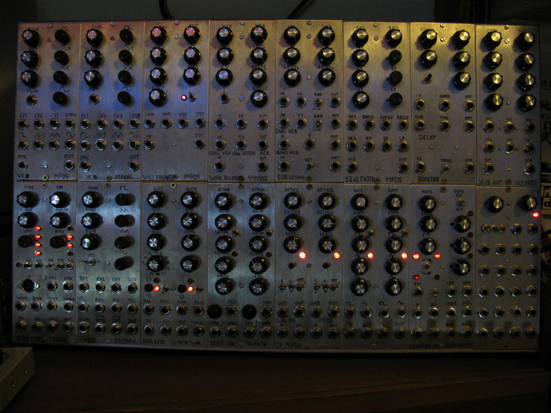
Hi everybody, After have build SEQ v4 with STM32F1 with options (ethernet / 4x IIC midi / AOUT/ BLM port) no wilba CS/ homemade frontpanel (lots of DIN DOUT) some years ago... (and working very well) I'm building a new SEQ V4 with STM32F4 and Wilba CS/schaeffer frontpanel with: Line Driver transmetter 2x MIDI IO IIC Midi ethernet card from the fist seq BLM port a separate rack with Line Driver receiver ,AOUT and DOUTx4 for gates/triggers Questions: I don't find informations for the BLM port with STM32F4! someone say on a forum that the second MIDI IO will be for this purpose: what is the best way to have BLM port with STM32F4? how to wire? Is MIDI IO with STM32F4 provide 3V or 5V midi ? (does the MIDI IO stuffed with 220 ohms or 47 ohms resistors R3 R5 R8 R10?) Is the config of LineDriver is Plug n' Play? you could use the seq without Line Driver receiver or have to plug parallel port permanently? Thanks