m00dawg
-
Posts
1,404 -
Joined
-
Last visited
-
Days Won
16
Content Type
Profiles
Forums
Blogs
Gallery
Everything posted by m00dawg
-
Being that this is my first board, I would be reserved to try and run a bulk order myself. Once I do have the board in my hand (and hopefully put together), we can see. But if nILS can put together a board, I'd say go with that. He can probably make a superior one to mine :)
-
Thanks for the clarification, /tilted/! I think I get it now. Your (nILS's) board layout IS for radial caps, but you are allowing for different sizes? As for the caps, I'll keep those in mind. The place I often get parts from (Allied Electronis) does not appear to have many of the ones you mention in stock though :( But I'll keep that in mind. I really like to use them since they have no minimum order and are SUPER fast due to where i live in relation to them. That said, do you perhaps have a part number from another site and/or link?
-
This is the type of capacitor I am referring to: http://www.alliedelec.com/Search/ProductDetail.aspx?SKU=8810456&MPN=SR205E334MAR&R=8810456&SEARCH=8810456&DESC=SR205E334MAR
-
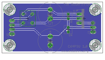
An even better modification. Now the board is noticeably smaller.
-
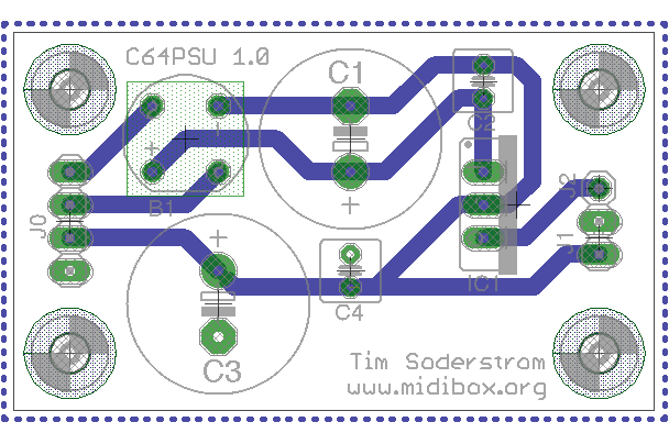
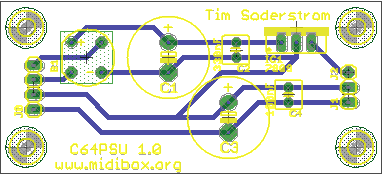
Ok, I applied some of the suggestions and have an update! I was able to cut down the size a bit more too by changing things around. The only thing I have yet to do is look at switching to the parallel mounted capacitors (I think I confused myself on the issue in my last post :). The ones on my version should be vertically mounted (radially?). Anyways enjoy. Flames welcome :)
-
Well if it took you two weeks, it'll likely take me months :) First things first, though, getting my bankstick and C64 PSU boards in my hands. If I can have success from there, maybe I'll start to venture out :) I don't suppose your CORE + 2SID design is going to be offered up to the general MidiBox community? ;)
-
I would agree! It's both science, art, and skill all at the same time. I already have a better appreciation for these things (and heck, I already had appreciation even before trying to build a board of my own). Heck, it's taken me over a week just to get this far with a fairly simple circuit :) It's exciting though! I can't wait to get this guy printed. If this works out, I think I may try to complicate things further and go for a CORE + 2 SID optimized board to be used for SID channels 2-4 on the MB-SID. I looked at the schematics, however, I figured I'd better take things one step at a time :)
-
Indeed! I didn't realized Eagle failed to connect runs if you run a wire over a point without stopping. I fixed those issues, and was also able to re-route items around the pin headers (for the most part) though I am still working on that. Got some more to do so I'll submit an update hopefully soon, though it's going to be a busy work week for me :/ Silly work getting in the way of awesome hobbies :)
-
Wow so much awesome information! Thanks nILS and stryd_one! I'm not sure where to start, so I'll jump right in: They actually require layer 29/30 (tStop/bStop) as well as the silk layers (they are created with a script that recommend running). The errors are actually for layer 29, and, you're right, if I hide them, there are no errors. Since their DRC step passed on their end, I assume it's probably nothing to worry about? Whoops :) Can't say I'm too surprised since I'm a fairly big PCB CAD newb :) I sort of guestimated based on the caps I purchased for the protoboard design of the board. They are the ones that stand up and are usually round at the top. Sort of like a stick figure without arms. Radial I think? The symbols you have are for axial right? Or no? I think I see what you are doing. So basically, it doesn't matter if I connect the +5V with the -9V right at the big capacitors? I didn't think so, but didn't want to waste a board design trying to find out. So thanks for clearing that up, though I was wondering if you can elaborate on what you mean by parallel and what lengths should be short as possible? Do you mean all lengths or, in this case, the small caps? If all lengths, now that I can connect the wires to the big caps, I can shorten the circuit even more. Actually, your board design is most of the way there it looks like :) F6, by the way, didn't work. That turns the grid off and on for me, but I assume you are referring to the RatsNest feature? I used that on a regular basis, but in this case, I wasn't sure if I could trust how it connected the wires since I wasn't sure about when I could combine voltages as noted above. Finally, I noticed that you used a ground plane. I had considered doing that (just like with the Bankstick board I'm working on) but I was a bit confused about how that would work or if I needed it for a power board. I probably should've thought about it more, since your solution looks obviously exactly like it should look :P I assume the general rule of thumb is to ALWAYS use a ground plane? And probably almost always use an isolation plane for a two layer board?
-
Well, on the Mac, it's easier to print to PDF I find :) Speaking of, though, here's the updated version! Bigger wires and in a format friendly for BatchPCB (http://batchpcb.com). The only problem I am having is the that the Design Rules says the Stop Mask is wrong. Not sure how to fix it, but BatchPCB's own DRC doesn't seem to be complaining about it. *shrug* c64psu.zip
-
Hah oh yeah. Duh. That was, indeed, the problem. After I plugged my M-Audio MidiSport 1x1 in, it worked. Just in case you need it, I'm running a MacBook Pro (OS 10.5) with the stock Java: MacDawgPro:~ tim$ java -version java version "1.5.0_13" Java(TM) 2 Runtime Environment, Standard Edition (build 1.5.0_13-b05-237) Java HotSpot(TM) Client VM (build 1.5.0_13-119, mixed mode, sharing) I do have 'mmj' installed as, without it, it does not detect my MibiSport 1x1 (which is the only MIDI interface I use on the Mac). I do most of my music stuffs with a Windows PC (but a good chunk of the MidiBox dev stuff on my Mac) so I will try the application on it the next chance I get. Shame on me for not trying that first :P
-
I thought about that too (for both this one and the BankStick board I'm working on). How much larger should I make them? I used the default of 0.016, but have plenty of room on this board to make them bigger. One question I had - when I route the +5V to the 7809, can I jump off the + of the 16V capacitor? The C64 Optimized PSU schematic shows the wire to be before the capacitor and not after, but can I go up to the capacitor? Reason being is that I might be able to tidy things up further if I can do that. Haha. Fair enough :) You got me. I was being lazy :)
-
Hi TK! Those screenshoots look fantastic! Alas, I tried to launch it, however, and was greeted with the following: MacDawgPro:MIOS Programs tim$ java -jar MBSIDV2_Editor_v0_1.jar Exception in thread "main" java.lang.ArrayIndexOutOfBoundsException: 0 >= 0 at java.util.Vector.elementAt(Vector.java:432) at org.midibox.midi.MidiDeviceRouting.<init>(MidiDeviceRouting.java:56) at org.midibox.apps.SIDV2librarian.SIDV2librarian.<init>(SIDV2librarian.java:44) at org.midibox.apps.SIDV2librarian.SIDV2librarianGUI.main(SIDV2librarianGUI.java:537) I thought it might simply be because I didn't have my MB-SID connected, but even if I did, I figured Java still wouldn't know which interface is for the MB-SID?
-
I figured while I am on a roll, I might as well try my hand at making the power-board for the C64 Optimized PSU. Thought I would offer it up for suggestion, or if anyone else wanted to use it! I could probably clean up the traces from the +5V to the voltage regulator but I didn't want to make any assumptions. Enjoy! Flames welcome! c64psu.zip c64psu.pdf
-
You think so? I picked the smallest traces that the auto-router used so I figured it might be ok. You are right though, I probably can work around the pins instead of in-between.
-
Wow. After having completely routed the entire board manually, I have to admit, it looks MUCH better! Hopefully I didn't do any wrong :) I am thinking about putting more of the wires on the bottom but otherwise I think it looks good! Thoughts? bankstick.pdf bankstick.zip
-
Well, my plan is to try routing manually this weekend, so, assuming I don't suck at it, I suppose that might be a good comparison. *shrug* I wonder why auto-routers suck so much? I mean, isn't that a task a computer is supposed to be able to do in superior fashion to humans?
-
Actually, I want to make at least one more board - for the C64 Optimized PSU, though that one is going to be even simpler (it's super simply on a protoboard anyway). I suppose I could have started with that one first...hmm...anyways. So the consensus is to DIY before messing with the auto-router eh? I traced the paths and the auto-router appears to have done things the right way, although it does, indeed, look pretty ugly. I'm going to try making a board manually hopefully this weekend to compare. This circuit is simple enough I don't think it's going to be all that crazy. I will say, however, I have WAY more respect for Wilba than before (and I already had respect for him :P). I have no idea how he was able to bust out his MB-6582 with one big board. This small tiny board has taken me more than a week now. Granted, while much of that is figuring out EAGLE, a larger board has to be an interesting affair indeed.
-
As promised, here's an update. I renamed it to MidoBox BSx8, although I guess it should be 7+1 or something (since one is meant to be external. Anyways, the wires are sort of ugly. I'll admit, I cheated a bit a used the auto-router and then moving things around manually. The result is, well, still ugly, but perahps less so. I also have a ground plane this time, as suggested. Thoughts, Suggestions, Flames? bankstick.zip bankstick.pdf
-
Well, in this case, is the clock a big issue for the BandSticks? If not, it doesn't matter how long the wires are, no? Either way, the board's pretty simple so I'm pretty sure I can route things by hand this time around.
-
The C64 PSU may be old, but I would still consider it as an option. The Optimized PSU is easy to and quick to build, and you know what you are getting into. I imagine that it is going to continue to run for some time in the future. Those things were built like tanks.
-
Awesome, I'll give that a shot hopefully today, or whenever I get to re-working this thing. I may rename it too. Bankstick 4x4 implies 16 sticks, when, in reality, it's just 8 :P I think I am going to use a header for only one of the banks though. I can't see a need to fill up all 8 banks internally and having the extra one would be convenient. That will also make the board simpler and smaller. Thanks everyone for all the help! Again, I'll post updates once I have them in case anyone wants to make their own, change it for their own use, etc.
-
Woohoo! I finally got tags right :) In terms of the auto-router, I assume I then just need to layout traces myself? Is there a how-to on how to do this? I basically just ran the ratsnest tool, followed by the auto-router. Not sure how to do it any other way :) That's weird because, when I set the text to be on the top, it was still backwards? Either way, I'll need to redo my board because I want the J0 header (the one that plugs into CORE) on the right. Not sure why. I just like it there :) Bad things I assume :) I thought about using jumpers, but I figured in a project like this, common sense would dictate not to try and use both. Granted, I can make the board smaller by doing away with the headers. I thought having bank 7 (or 6, depending on how you are counting :) as the external one and just have a header there. So there would be 7 on the board, 1 being for the ensembles if using this on a MidiBox-SID (which is where I plan on using it first).
-
Thanks for all the help! I will definitely look at the ground plane (I assume the new board layout uses that, nILS?). I see a bit of a conflict over using the auto-router or not :) I haven't really figured out how to do it manually but I don't suppose it would be that difficult. I am still confused about the board view. It is looking at it from the bottom right? Which is why the text is backwards? As far as the schematic, it too, makes things look much better. I used the junctions so much because I was getting warnings all over the place initially, but I now see what you're getting at. I didn't realize you could use the GND and V connections that way either :) @SLP: To elaborate a bit on the pins, it's an either/or setup. So you can use stuff the socket with a chip OR use the pin headers and route them to an external connection. That way you can use a mix of internal and external banksticks. @cimo I do plan on having the board printed. I have not looked at the costs, but I've heard it's pretty cheap to do these days and I would much rather have a real board over a protoboard where possible. I suppose we could try to figure out a bulk order if people want to go that route if that is what you were implying, but I don't know that I'm the best person to coordinate something like that, given that I still consider myself somewhat of a newb. Anyways, I'll go ahead and make the changes and push another revision out here soon. And I like Moron Resistant. That should be on a shirt man!
-
So I think I am close to finishing my first board in EAGLE (holy crap the auto wire routing feature is awesome!) In this case, it's a multi-bankstick board. In this case, I wanted to have the option of putting the chips on the board itself or externally. So, the board has both for each bank, of which there are 8. I *think* the board is in relatively good shape, but figured it might be wise to see if someone might want to take a look? :) I'm a bit confused as to why EAGLE is looking at the bottom of the board (I assume that is the case anyway, since the text is backwards) so I'm a bit worried I may have done something there :) This is one of the boards I wish were available from Smash, so if I can get this right, I think I'll be pretty happy. And, of course, I was going to give the EAGLE files out so others can potentially use these as well. If this board actually works, I was then going to make a C64 Optimized PSU board (which is probably going to be even simpler than this board). bankstick-board.pdf bankstick-schematic.pdf bankstick.zip