
rosch
-
Posts
705 -
Joined
-
Last visited
-
Days Won
1
Content Type
Profiles
Forums
Blogs
Gallery
Everything posted by rosch
-
:D no unfortunately i don't speak dutch, but it could be i'll try to learn it some time, because i like it very much. and it's very close to german, too, as the quote shows!
-
:) thanks!! cool tracks! #1 is my favorite
-
we're trying to get enough interest for this one. optrex green on black.
-
yes that's how i expected it. the other kbd has it that way. the bars are in the front of the keyboard and the pcb on the back. and i thought this one would be the same, but as i got the photos i was surprised that there are no bars at all. perhaps this one was from the 2nd organ and it has a different technique ??? i think i'll have to wait until i can measure it to see how (or if) it is working. time to think about the modules i need...
-
well i haven't done it yet. i think all one has to do is find out about the pins of the LCD, make a ribbon cable and attach it to the core. i have to do the same with the LCDs i use now, too. or have i missed something? ???
-
oh yes red on black would be fine, too. but there's a much higher minimal order quantity if i remember that right?? good thing is, it's easy to change a lcd afterwards!
-
sammelschienen: i'm curious to see how these keys function because there are actually no bars (sammelschienen). when i'm at home i'll also post a pic of the other small cv kbd which has them. the brass wires on the picture don't move, i have cut them off a resistor ladder pcb that went all along the whole length of the keyboard. and if it is possible to use that kbd i intend to wire them just as they are now on veroboard and do all necessary scan matrix connections (diodes etc) on that board. so i hope that i will be able to use it. at the moment i think that i might keep it even if it is not possible to obtain velocity response with this one.
-
really awesome. very decent design! how did you implement the keyboard?
-
thank you very much! :D they arrived! btw do you also plan doing the other standard sizes like 2x16, 2x20?? thanks again!
-
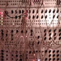
ok here are the pics:
-
no no you were right, i just removed the resistor ladder. i shortened it to 2 oct and made a little cv keyboard. the resistor ladder had been substituted by trimmers (spindeltrimmer) because of the non linear behaviour of the vco (it was meant for a tube synth). but today i had my father take me some pics of the keyboard i'm planning to use (i'll have to wait a few hours to be able to put them here because i'm still in some other mass upload) and it turned out to be a bit different to the one i had used for the cv keyboard back then: this one has no graphite bars, just again several brass wires per key (which i already disconnected from their resistor ladder pcb) as well as "some 4 or 5 wires that come out from the side". so i assume there must be some switches already integrated in that keyboard (i took apart 2 old philips organs actually). and i think i'll have to wait till i'm there to take some measurements to see how those keys work. so, pics will follow some few hours later!
-
thanks for the interest guys! clem! i noticed you deleted your former posts, but trying to bookmark your thread i found out i had it already there. the way you built your keyboard reminds me a lot of how mine functions too, it's a shame that i do not have a photo right now. i'm very interested in how you solve the problems. lucem: very interesting video, again ;) i don't know much about the fatar until now and which features they provide (will have a look at them). but i always thought every key to have 2 tactile switches arranged in a scan matrix to get the velocity from. as far as i can see there should be no big difference to mine (after replacing the strange graphite sticks with a copper wire) except that i can have more switches that way; given, that some close reliably faster than others, which i'll have to find out. but even if this is not happening without further mods i just could position one copper wire a bit higher (should even work with hot glue). but of course it may easily be that i'm missing something important here. but if it is possible i'd like to do it myself rather than buying a prefab keyboard controller. i'll try to find & learn more about scan matrices in the next time, especially about QBAS' and see which exact project i will actually need for this... /edit: typo & better understanding
-
i was wrong... this changes everything ;) good luck guys!
-

Looking forward to building a Midibox SID V2 but...............
rosch replied to tb303orys's topic in MIDIbox SID
yes it is the baseboard part kit, afaik it should contain all parts that mount directly on the pcb. there's also a conrol surface pcb you can purchase. you will still need other parts like encoders, leds, lcd, housing, psu, tact switches. but you'll find all info you need to do the purchase on Wilba's DokuWiki page: there you can compare his part list with the list in SmashTV's store and learn about what is needed in addition! there have been many 6582 builts, try the forum search on this, you'll find a lot examples. -
hi! you could do it in the Bulk Order section and maybe link from there to an additional thread in your language category... but if you look around the forum you'll find some people who created their custom pcbs for several projects and had them shipped (e.g. from china) for a good price. edit: but "Sale Requests" is definitely the wrong section to post this in (here you would ask for permission to sell a midibox device for no profit)
-
yep, germany. no problem, but as i said i can't really guarantee that i have a pcb left. basically i bought more than i needed because i wasn't so sure about SMT soldering... and already shared some. now i actually need more because there are now very interesting projects which do use the GM5. but this is also no rush, i can wait until the next bulk order is happening.
-
midibox can drive this lcd or a touch sensitive lcd panel?
rosch replied to wavewalker's topic in Parts Questions
http://www.midibox.org/dokuwiki/ http://www.midibox.org/dokuwiki/doku.php?id=home:mbhp:module:lcd&s[]=lcd http://www.ucapps.de/mbhp_lcd.html and if you try a forum search for "LCD" or "display" from the main SEARCH page (button above) you may find a lot of info in threads! -
just found this link
-
sources for new PICs (pre-burned): PCB-Mike's Shop, Germany SmashTV's Shop, USA you can purchase the chips from both, actually no matter from where you are.
-
hi! i should have a spare chip and maybe even a gm5 board, but i'm not at home for another month so this would not be too soon, too. you could have a look at the responses to other similar requests in the Fleamarket section, you still might find someone... but if you like to make things faster you could write yourself on that list with a couple more than you actually need ;) http://www.midibox.org/dokuwiki/tk_gm5_bulkorder i'm again on the list too, though i already got some. as you can see there's no problem getting rid of overstocked GM5!
-
hi! you'll find your answers in the DokuWiki parts FAQ: http://www.midibox.org/dokuwiki/doku.php?id=parts_faq and on the wiki page of Wilba's 6582 you'll find also an example with name, manufacturer and part number of a possible switch: MB6582 CS parts list
-
interesting! i'd like to use a keyboard i once salvaged from an old 70ies Philips Philicorda. one side has a pcb with the resistors. the other side has for every key 5 or 6 very thin brazen tongues which open (each tongue) a contact and then close another as long as a key is pressed. it has 10 or 11 parallel contact rails (metal bars surrounded with sth like rubber with graphite) KEY DOWN || || 1st bar O \/ 2nd bar O BRASS TONGUE : : i do not know the exact number of contacts for i'm not at home atm (therefore the sketch instead a pic). but it's even possible that some contacts close faster than others (hope). when i replace those graphite-rubber bars with 1.5qmm solid copper wires (easy to do, the bars run through plastic holes) i could switch e.g. sth to ground by pressing a key. that should work, i used the same (just reduced to 2 oct) for a CV keyboard, the copper wire works fine. anyway i'd prefer such a solution to buying that doepfer controller, as you say, i would not learn anything... (when i'm there again i'll make a pic of the keyboard)
-
hey very nice work! the surface & wooden frame look great together! i'll have a look at your DokuWiki!
-
crabs :o
-
fussylizard 2 (?) strophlex 3 nsunier ~10 rosch 3 ssp 2 (maybe 4) gtxdude 2 ---------------------- ~22 if interested, feel free to add yourself!