latigid on
-
Posts
2,524 -
Joined
-
Last visited
-
Days Won
149
Content Type
Profiles
Forums
Blogs
Gallery
Everything posted by latigid on
-
The power options are: 5V vreg, could be left out +5V rail from the case USB (power only) DB-25 cable (can suffer from voltage drop, thin wire)
-
80 DOUTs are possible (8 gates, 8 clocks (including start/stop if you like) and 64 triggers. That would push the SRIO chain to 20 SRs, which I think should still be okay. CV is 8 channels on the SEQ. Not measured yet, but the only hungry thing might be the Vreg. All LEDs are driven from the +/-12V rails.
-
Seems like it should work: http://ucapps.de/midibox_sid_manual_cv.html I thought the 8 gates would be on J5s, but apparently you can also assign them to a shift register. This means that you can use the J89 on the LineTX, I guess connected to the end of the SRIO chain. You would probably need to build a new firmware .hex file. J6 on the MB-6582 would connect to the J19 header on Line TX. The pinout is different but you can use flying wires or DuPont cable/hot glue. Seems like the Line TX should fit in the Pactec case. If it hits the CS PCB, then you might find another location for it and use the alternate 26-pin IDC header with a corresponding DB-25 ribbon connector.
-
Can't match Peter's video skills, but I hope this gives you an idea of the Expander modules.
-
Okay, I changed the IDC8 connector for an Amphenol part in the BOM; at least in the datasheet this is 0.1mm wider. 649-71600-008LF It should be black and the stock availability is a bit better. If anyone orders and it's not okay, please post your experience.
-
One idea is to try another brand of shrouded header, e.g. 710-61200821621 from Würth 30308-6002HB (the corresponding 3M pin header) is has no stock available, but it might be worth ordering a piece and letting Mouser know :).
-
Congratulations on a great build and thanks for the feedback! Was this in the tutorial video? BOMs "default" to the LH case version for cable lengths, but the recommended cables are fairly okay. Interesting, as the part series is the same for all IDC female connectors. Maybe a consequence of lesser friction with fewer pins? A little hot glue or fixogum would help here. If there are further complaints/concerns I could look for another part. Do you have the reference/supplier for the one you are using? The cabling is tight indeed. The newer case plate has a small cutout so a right-angled IDC can be used, with the cable running straight down. This will be documented by Peter at some point. Those with older cases can use a piece of kapton tape or similar to isolate the OLED PCB. Nearly there!
-
Good work! After ~10 years of soldering with a conical 0.5mm tip, I have recently discovered the joy of a 1.6mm chisel tip. It really is night and day with SMT as you get great heat transfer to the flat pads (always heat the pad if possible), then apply 0.5mm solder to the pin et voilà! With a conical tip I always had to use the side of the iron for SMT and the heating was much more tedious. Still the conical tip is better for larger THT components, pots and jacks etc. I have both irons at hand and just plug what's needed into the soldering station :)
-
I'm glad it was something simple. For the TPD, you can't display both the Activity Matrix on the JA board and the external TPD matrix. You can probably assign the extra buttons and LEDs/segment displays on the TPD though.
-
It's been a while, sorry. The same jumper is on the Line Transmit board, is it closed? You have the option of external power, as there could be losses through the DB-25 cable. I've added the info for both boards in their respective BOMs. Sorry for any confusion.
-
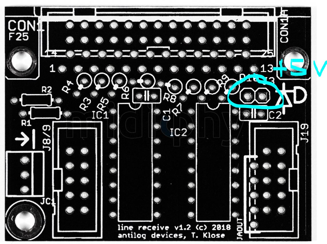
There's no option to disconnect the +5V on Thorsten's design.
-
Old receiver lacks this one, otherwise it's functionally the same.

-
Not a good sign. How is the AOUT_NG being powered? There's an extra jumper on the midiphy Line Receiver that connects to the +5V buss. Is it closed? Wrong cabling? Let's see a photo of your setup. What Line Driver boards were you using for the older SEQ?
-
Let's see a hi-res photo of the board.
-
Seems to be intended: there's a BOOT1 solder jumper on the rear bridged to 0V. 407v schem is here https://www.waveshare.com/w/upload/5/58/CorexxxV-Schematic.pdf Could be worth doing some pin tracing.
-
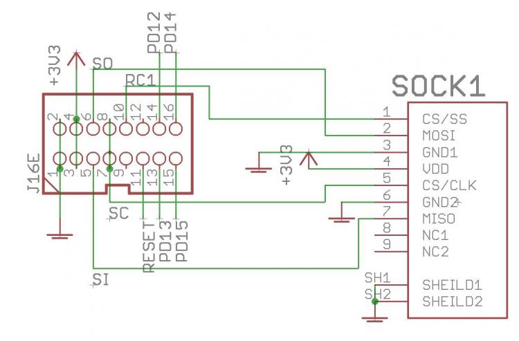
I'm not sure if there's a tool for SD card diagnostics. There is a dedicated app for a "mass storage device", but it's only built for LPC/STM32F1. Sockets look okay Worth a try. Once when soldering a DISCOVERY F4 Core, my sockets were overheated. I don't know exactly what happened, but the SD card actually overheated and burned up somehow when I inserted it. Take care when soldering the socket. If you can't manage the smaller pins (in the datasheet they have function names, not pin names) then try leaving them unsoldered. They aren't connected to the pin header (NC in schem). It might also be possible to overheat when soldering down the IDC shrouded header. The 32MB would be perfect! It might be useful to have a blacklist/whitelist of SD cards. At the moment I think mine are 4 GB, not sure of the speed. The cable is assembled correctly but the leftmost socket might be skewed (or the cable was cut on an angle or it's an unhelpful camera angle). Check for shorts on the cable (e.g. by plugging into the sockets). Note that some pins are intentionally doubled up (see schematic).
-
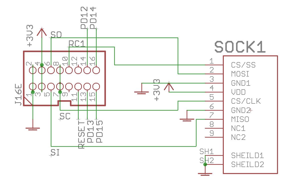
Please provide pictures of the boards, cables and the make/source/sizes of SD cards. Did you use shrouded headers? If so, you can't plug the cables in the wrong way, unless they're incorrectly assembled. Try to format using some sort of FAT setting. Is the format successful in Windows? Not seen before, but I guess so? You could've damaged the SD card, the MCU pins or both. Again, can you still format the SD cards or are they unresponsive in Windows? That's right, but above you were saying that maybe the cables were backwards? Were they incorrectly assembled before? Shrouded headers or not? See above comments J16E carries the LED signals too. If there was a "backwards cable", then something funny could've happend there. But you don't get many LED signals with _NG. More are active with the SEQ app. Here's the schematic. The SD card pinout follows the datasheet that you can get from Mouser. Check for continuity of pins back to the Waveshare 407v board (with the power off). Check that adjacent pins are not shorted. Make another cable or use the one from an OLED at least temporarily (don't use the OLED cable!) You can measure voltage at the SD card. You won't see much with a multimeter on the other pins, but you can use a scope or logic probe if you have one. Also, it is possible to overheat these SD sockets. What temperature settings did you use? Were you heating the pins for a long time?
-
Try to format the card, I think FAT8 is the best. Then try again. If you've used shrouded headers, then the cables will always plug in the same way. When making IDC cables, ensure that the notch/nub points in the same direction relative to the cable strands unless otherwise noted. Some SD cards don't seem to work, e.g. if the size is huge like 32 GB (MIOS will use a very small fraction of that).
-
Hi Niels, Good progress so far! You can use the same .NGC for testing everything together. Or if you switch to R, then use seq_r.NGC https://github.com/midibox/mios32/tree/master/apps/controllers/midibox_ng_v1/cfg/midiphy Best, Andy
-
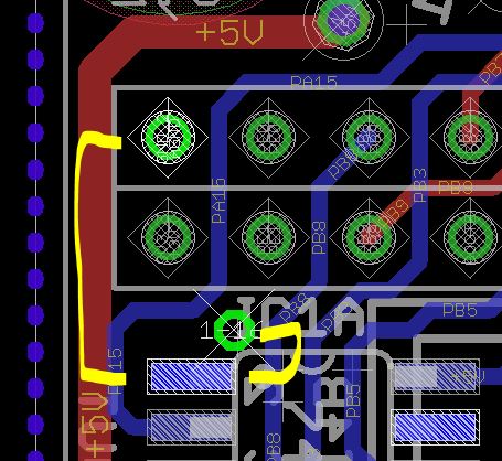
If you don't measure continuity from 0V (ground) to the pin, you can run a bodge wire as shown. This is viewed from the rear of the board. The via is tented, so the pin on the 2x25 header might be better, but you'll have to go around to the other side of the PCB (the headers are on the same side as the IC).
-
J15 sets the OLED voltage, which should always be 3v3. Peter's done it with a USB power bank. I think the total draw was 0.8A or less, but best for Peter to check in.
-
No problem. From your SMT soldering and parts placement it looks like you've taken a lot of care with the build. Some of the THT pins look like they might benefit from a bit more solder, so make sure you have a proper solder filet from the pad to the pin. Could be the light/angle of the photo though.
-
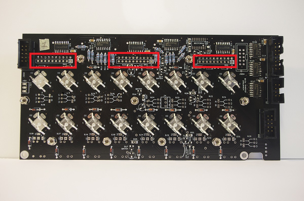
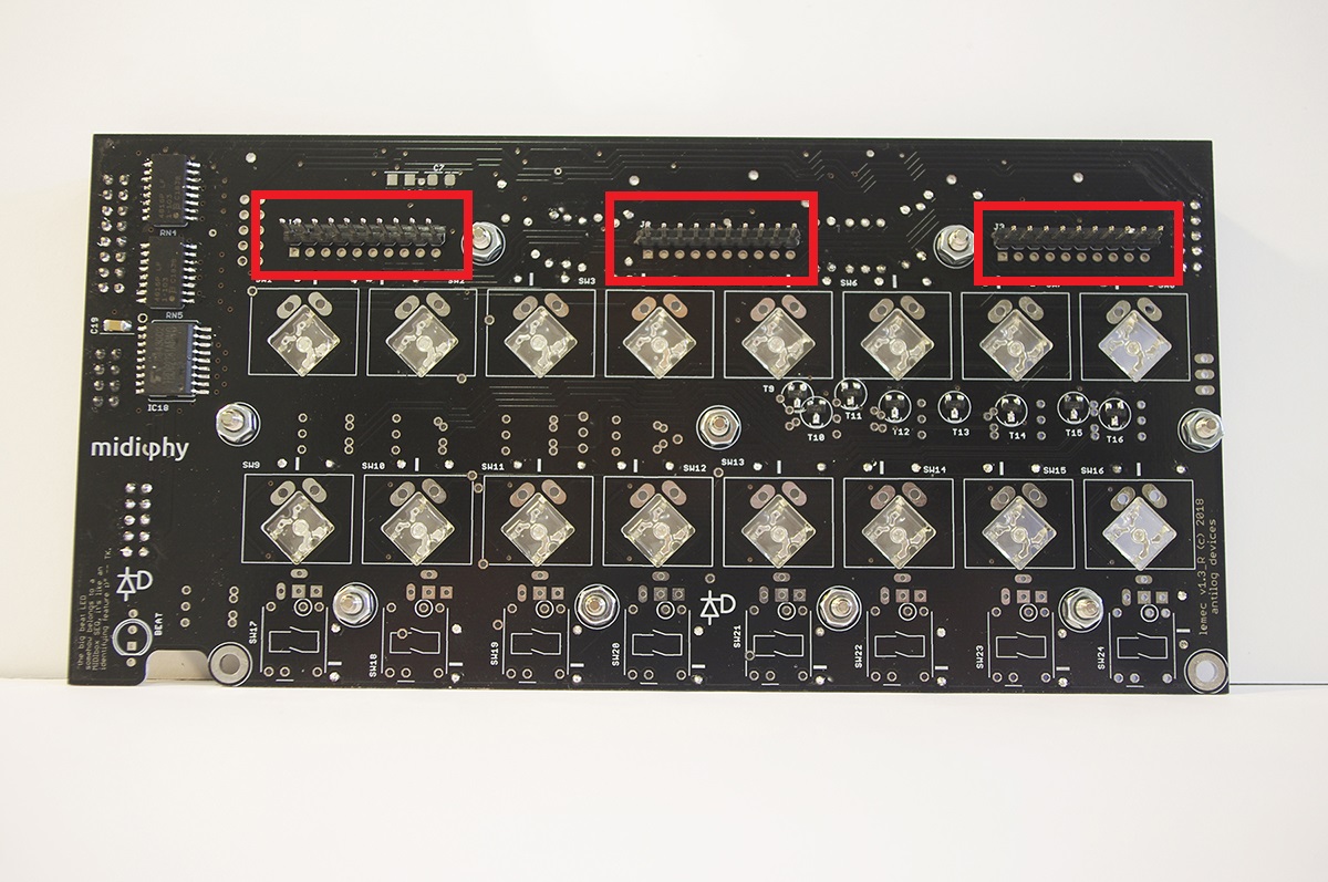
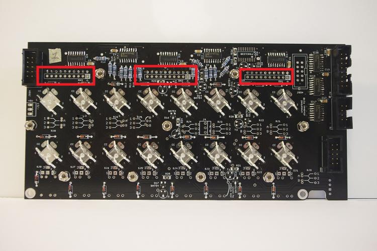
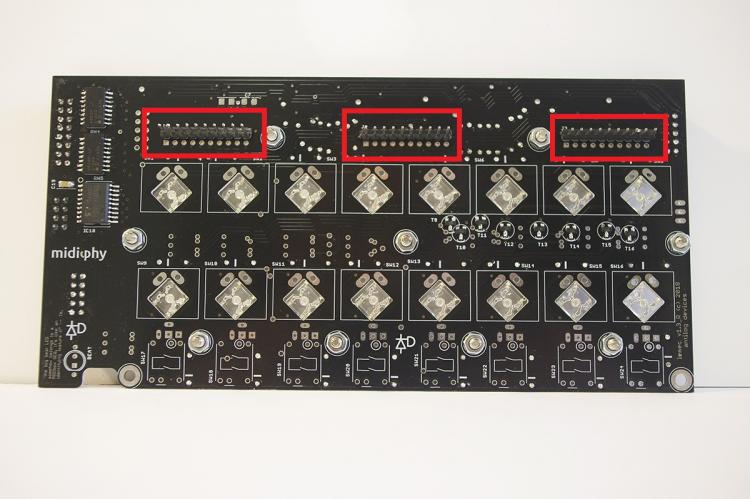
I'm pretty sure your problem is that these parts are not installed. Make sure that you do have bussed resistor networks (9 resistors, not 5 resistors) and align the dot with the marking on the PCB (ask if you are unsure).
-
Are the 10-pin resistor networks soldered?
-
1. Please edit the post to not include such a long string of DIN messaages. A few lines will suffice. 2. Please upload the images to the forum so others can be helped when the offsite links no longer work. The typical error here is an incorrect part or soldering for the 10k resistor network on the JA board (see previous posts in this thread).