

latigid on
-
Posts
2,524 -
Joined
-
Last visited
-
Days Won
149
Content Type
Profiles
Forums
Blogs
Gallery
Everything posted by latigid on
-
 The bootloader is not correctly flashed onto the F4, so it's no surprise you can't get anything to stick using MIOS Studio. This includes holding the blue button: you are trying to enter a bootloader mode that doesn't exist. Did you try wiping the flash with the ST-link utility and re-flashing the MIOS bootloader over SWD? The USB micro is only needed for USB updates after the initial flash. The USB mini is required for initial bootloading and can supply power, but it's not required after the booloader is installed if you use the power jumpers on the Core or manually with a dupont wire.
 -
Normally it should be plug and play. You could check for continuity between the SWD pins of the ST-LINK side and PA13/PA14. Also check that no adjacent pins are shorted together (on the MCU) nor shorted to 0V or +5V. https://www.st.com/resource/en/schematic_pack/stm32f4discovery_sch.zip You shouldn't need an SD card, just USB power jumper is needed.
-
Just to confirm, you are using this file? http://ucapps.de/mios32/mios32_bootloader_v1_018.zip And the correct version (F4)?
-
Here's the cheapest 560R 5% one on Mouser: 71-CRCW1206560RJNEB We use thick-film, 5% ones, because the value and Tc is not so crucial.
-
I guess the bootloader is not correctly installed. Try again with ST-Link (update firmware).
-
What Core version? Discovery board? Reliable source? Did you update the ST-Link bootloader first? You also have to restart MIOS Studio between hex updates.
-
Welcome! Thanks for your parts suggestions. You may also like to check Reichelt and Conrad for the MEC parts, if they offer cheap enough shipping to France? The 560R is not a crucial value, and in fact could be made as a 500R resistor by stacking 2x 1k resistors on top of each other. 470R should also be okay. Best of luck with your SEQ v4+ build!
-
It would be better to see the actual connections or even a photo of the circuit... Presumably the transistor base is connected to the 220R resistor of a DOUT pin? Normally I use 1k resistors for setting the NPN base current, but it probably doesn't matter. Plugging something into the jack might create a voltage divider? Also, this circuit is trying to source current out of the NPN. The LED/resistor should rather be connected to the collector.
-
I see, I missed the minit part and assumed minimoog. First, you need to get the range okay, then the rest is done in software. It is a non-standard tuning so some modification would be needed.
-
The range should be over 10V pp. The issue is that the summing circuit in the AOUT_NG is not optimal, thus you don't get the full range out. See the following for an explanation and workarounds:
-
Feel free to post/link your circuit and I can see. Mine is quite different though and uses buffers etc.
-
Cases are there and are going fast!
-
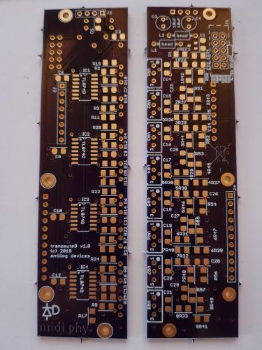
Thanks for the feedback! Re: AOUT_NG: in the MIDIbox paradigm, CV/gate is split into AnalogueOUT and DigitalOUT modules. The assembly above is the DOUT side, which was previously available as a PCB build using a DOUTX4 module, but you needed to provide your own 3.5mm jacks. There have been various solutions over the years, like using Ken Stone breakout PCBs, also Altitude did a combination that had eight each of CVs/gates/clocks/triggers. The AOUT side will be a different design to AOUT_NG. I had a previous incarnation in through hole, but this version is more compact and simplified. (The other one had CV range switches and fine-tune control, but was only four channels in I think 10HP.) Here's a teaser of transmute8 fresh from OSHPark (thanks for the image Peter!), not tested and won't be for a little while. Hope you like 1206 resistors (or 0805 if you wish!)! Best, Andy
-
dinx1 DINX1 on MIOS8 no load signal on RC-line?
latigid on replied to synthesizerbauen's topic in Testing/Troubleshooting
Yep, should be the other way around. SER is an input, and the data flows out QH back to the Core. -
dinx1 DINX1 on MIOS8 no load signal on RC-line?
latigid on replied to synthesizerbauen's topic in Testing/Troubleshooting
If you have an F4 32-bit Core, you can use MIDIbox_NG to debug DINs. The RC "pulse" at pin 1 should be every 1ms I think. Check the wiring/stripboard layout? Check the correct signals are sent from the PIC J9 (I think). -
dinx1 DINX1 on MIOS8 no load signal on RC-line?
latigid on replied to synthesizerbauen's topic in Testing/Troubleshooting
CLI inhibits clocking in of data. If it floats, probably nothing will be read. SH should be high "most of the time" as this sends a constant data stream, even if the tail is empty. When RC pulses low, the inputs are read and shifted out. The number of SRs shouldn't matter. Did you try "set debug on" in MIOS? Not sure if that's enabled for PIC uCapps. Maybe there's another app you can test? -
dinx1 DINX1 on MIOS8 no load signal on RC-line?
latigid on replied to synthesizerbauen's topic in Testing/Troubleshooting
What is pin 15 connected to? Should be 0V (ground). Please draw a nice diagram of what you have stripboarded, or compare carefully with the DINX1 schematic. Normally, pullup resistors are used. What are your switches switching to? -
I attempted to come up with a "standard" controller and TK. worked on the hardware a bit. I even have some of the control surface PCBs left if you would like to try, however I don't think the idea as it stood will be pursued any more. The fact is that an iPad or other tablet running Lemur gets you 90% of the way there and might be nicer than a 20x2 LCD? You can use SVN checkout software such as Tortoise to get the source and compile, no worries.
-
Prototype of an 8x "DOUT" module. It is a simple build of two stacked PCBs called "binaire" and "octal". I reckon it can be done in an hour or less. In the SEQ v4+ context it can be configured as 8 gates, in combination with 8 CVs (in the works) 8 configurable clocks, or 7 clocks plus one start signal 8 triggers. Up to 64 triggers can be generated with the SEQ! Each output has an LED that illuminates with a positive gate. The modules are designed to be easily chainable, so decide how many are needed in your system. 4HP width. It would also work with other SEQ versions. More info to come!
-
At least on Windows you should power cycle the Core between updates. (EDIT: I mean close and restart MIOS, the MCU is automatically reset after updating.) If you really can't get it to boot/be detected any more, JPA0 is there to help on the wCore PCB. If you stuff this jumper, the bootloader will hold during startup. Normally you can then flash in another .hex again.
-
-
-
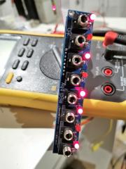
From the album: midiphy_euro
midiphy gate/clocks/triggers module, 4HP -
Schade/dommage! You might be able to remove the Matias switches (if really necessary) with your soldering iron heating both pins at once and pulling it out with the other hand/use a vice. A simple vacuum pump can also work wonders. If the LEDs still work, then the sink side of the matrix is okay. Not sure what could be fried just from pushing together.
-
Hi, On lemec_L, left side and both versions, right side, the encoder can touch the header pins. Best is to trim both sides (encoder pins are easier) first and also put a piece of kapton tape or similar between. From the sounds of it, you followed the testing procedure and had all DINs working before soldering in the Matias? Please try to isolate/insulate first and see if that fixes the issue. You can also check if there are longer through-hole components (especially diodes) that short out in beween. If not, please upload a good photo of the rear of the assembly and I will try to help.
-
Cases should be ready any day now. They were undergoing final painting this past week. The supply will also be limited, but the next run will be larger. Please consider that we don't have a proper warehouse, so it's impractical to store dozens at a time. We also made a slight revision to the plates to make OLED cabling easier. We understand that the cases are proving to be the bottleneck and we're working on the supply. Thanks for your patience!

