latigid on
-
Posts
2,524 -
Joined
-
Last visited
-
Days Won
149
Content Type
Profiles
Forums
Blogs
Gallery
Everything posted by latigid on
-
Nice!
-
A typical construction technique is to manually push LEDs into the panel and then solder. You'll probably have to do this anyway considering the height of other parts. There's a ready-made driver for MIOS32.
-
You could always get a panel laser cut, that way the corner radius could be 0.15mm or less. That's fairly much square. If you push the LEDs through, the corners might also be "shaved" off in the process, no issue! We stock a quality white OLED. Simplest would be to use this with a red acrylic "gel" or even have the whole window milled from transparent red acrylic. Are you using MIOS8 or MIOS32? The OLED driver works for MIOS32 but I don't know about MIOS8.
-
Well done! I think yours is the first green-blue one, will be nice to see it! Best, Andy P.S. cheers!
-
I recommend to use a soldering iron to keep the heat away from the semiconductor dies/wire bonds. If you use hot air, perhaps bake the LEDs at 80°C overnight to lessen the chance of failures (steam microbubbles might cause issues). Note that I haven't tried baking the LEDs, so YMMV.
-
Makes sense! SJ pins correspond to the numbers on superflux LEDs: 1=red 2=green 3=blue. As you're not using the red superflux LED, you should instead jumper SJs to pin 2. This connects the MEC LED to the A pin on the RJ, so the hardware configuration should stay the same. (this assumes that SJs A connect to 2 and B to 3)
-
Pin 1 is correct for SJs. Unless you're using a different RJ config, such as green and blue LEDs? Picture would help to clarify. Then are you sure about LED orientation? Check with diode mode of your multimeter. Red lead to circle, black lead to line on the MEC switch silkscreen should illuminate. Some have had problems over-stretching LED legs causing them to break. It would be odd for all LEDs to break though.
-
Missing/misconfigured SJs perhaps? Photo of the board?
-
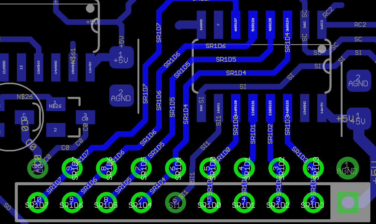
I can't offer an explanation that would have a problem isolated to SW18. If there was an issue with 165 ICs, then the whole column wouldn't work. If there was an issue with transistors on the sink side, then the whole row of four wouldn't work. My immediate guess would be that the diode is soldered the wrong way around or with cold joints. Could also be a faulty diode, but it's very unlikely. This is viewed from the top of the board. I've numbered the pins of SW18. Pin 1 (+2) is the cathode pin (also used for the LED). The connection should be common to the other switches SW17/19/20. If the marked bridge on SW19 is not present (i.e. no switch or bridge wire), then none of those four switches will work. Pin 3 is the DIN input. It should connect to the diode adjacent. The diode anode (i.e. non-striped end) should be common to other diode anodes in the column (i.e. on SW2/10).
-
Hello, just on the road at the moment, but you might try to check the connection made with a MEC switch. It is marked on the silkscreen as 'sink bridged by switch' or similar. The problem would be the same for all SW17-20. Test for continuity over that line and insert a bridge wire or solder the switch in if needed. Are any other switches not functioning?
-
happy it was a simple fix! No worries!
-
Hmm, I think that's the wrong part. The bussed network has a "2" prefix. Cross-check the part here: You should have only one piece of 652-4816P-T2LF-10K and two of 652-4816P-1LF-10K . Best, Andy
-
suggests the 74HC595 parts are correctly soldered. suggests floating digital inputs or similar. Are you testing the JA board by itself or hooked up to lemec_R? The shift registers are not located on the JA board. Check pin 16 of the RN is connected to +5V. All 165 digital inputs (pins 3-6, 11-14) and pin 10 should be at +5V, possibly excepting 5 and 6 connected to the encoder. Check for continuity between DIN pins (they should typically not be connected). What is the part number of the RN just to be sure? Photos would help, and a common problem is that the cable is not assembled properly. Try again with another cable.
-
This one confuses me too. The blue button is the "boot hold" function, used to repair a corrupt upload or other. What you want to do is upload the bootloader app, which could be done from boot hold or the normal flash. Thereafter load _NG again.
-
The red LED continues to blink, no issue there.
-
You need to update the firmware of the ST-LINK, then it'll work properly after.
-
Thanks for your concern. Schematics are provided when needs arise. This gives valuable insight to me so I can provide directed help, which I normally do very quickly as seen in the troubleshooting thread. If it happens that I can no longer help in this way, I would provide them to people who purchase the boards and the builders would need to figure things out themselves. It's good to know where the tricky points are as it can help for future projects. You don't need my help for this, simply assemble a chain of DOUT and DIN modules and assign the functions in the hardware config file. You can use a Disco board for a SEQ v4/v4+. Have fun!
-
Connecting a +5V power source to any 3v3 lines will do it.
-

The HAARP, a Hardware Advanced Arpeggiator.
latigid on replied to Antichambre's topic in MIDIbox User Projects
Looks well thought out, nice job! -
Cheers! Don't worry about the other board, the main thing is the SEQ lives! Well done! You can change the so-called TPD mode by navigating through Utility > Options #11. You can also test the hardware with SEQ_L.NG again; the CC 16 slider should light up the JA matrix.
-
Hmm, 2000 posts How is pin 1 bodged? Do you measure +5V to it? I would bridge to the empty J89 socket, pins 3/4. You can see the wider trace to it in your image.
-
Solder bodges like this are not very reliable. Rather I would use a piece of insulated wire and really make sure that you're properly connected to the RN, also that the trace is not shorted to 0V (there is a ground plane everywhere) or to +5V (less likely). You may have, for instance, shorted the +5V rail to 0V, causing nothing to work when plugging in that board. Not that the SIL header 0V connection sits close to the common +5V pin of the RN. Floating 165 inputs resulting from no connection to a pullup resistor could explain your random DIN triggers. Check that all pins are properly connected (view from the rear of the board). You should measure about 10k to the common pin on RN1. Soldering on ICs could be much better. The blobs on IC2 indicate too much solder and potential cold joints. You can wick off the rest or even try with a solder pump (here be careful to remove any "splashes" of solid solder that come out). It might be the camera angle, but soldering on IC3 looks like some pins may be shorted or close to it. You'll get it, don't worry :).


-
Your board has some "bodges" correct? Are you certain that they all make the right connections? Post some pics and I can check. Good that it's better. It suggests that the soldering on all points could be investigated. IC17 is certainly connected to the same power rail as all other ICs. Remember that CMOS ICs can be parasitically powered by data signals, so verify the connects with the power off and reconnect as necessary. Sorry, this refers to the parallel inputs (pins 11-14, 3-6). The input states are determined by the encoders and switches, so sometimes you might get 0V on an input that would change if you turned the encoder. The advice was more for checking IC3, which should always have +5V on the switch inputs unless one of a row is depressed. These state changes can be monitored in MIOS Studio with set debug on or monitoring DIN switch/encoder events. As before, the common cause here is floating DIN inputs resulting from poorly soldered resistor networks (cold joints or incorrect polarity). Another possibility is that pins of the 165 are shorted together. Imagine if the clock line was shorted to an input, like pin 2 to pin 3, then you might get a weird feedback loop, or if pin 1 was shorted to pin 2, which would shift in the inputs on every clock. Did you swap the cables?
-
Nicely done! Good lesson! Always WTFV (watch the full video). I think the video is shot in 4k or better? So you could always pause and zoom? Can you zoom on YT? There are arguments for/against. Ultimately it is up to Peter to decide. Note that there are bookmarks for all chapters. Good advice, I can think about an FAQ thread/post to summarise the most popular errors. Low before high! ? Good tips There's a list of cable lengths comprising once part of the BOM on the shop website. A personal taste thing, but you can always make it your own :).
-
Sure!