latigid on
-
Posts
2,524 -
Joined
-
Last visited
-
Days Won
149
Content Type
Profiles
Forums
Blogs
Gallery
Everything posted by latigid on
-
Looks like a nice chip, worth a try! Pinout is much better than a 595.
-
Cool! Normally issues on the activity matrix are related to a dodgy cable or soldering on the ICs/resistor network.
-
Unmodified _L should be used when JA is connected on the left. Unmodified _R should be used when JA is on the right. Modified _R should be used when lemec_R is the first board in the chain. You can of course freely modify the .NGC files to suit the configuration. Pin 1 being the dot marker? The resistors should connect in parallel to the common pin. You should also measure about +5V on the 165 inputs and they shouldn't be shorted together. IC17 should be connected to power. There are two larger plated through-hole vias that you can consider using.
-
If there is a systematic error here, please provide all of the info possible, especially the voltage outputs of 595 registers, results of NG tests including manual control. Random trigger behaviour can indicate issues with the DIN shift registers. Check that all resistor networks are the correct type and properly installed with the polarity mark aligned with that on the silkscreen. Check soldering once again, check and swap ribbon cables. Did you reload _L.NGC and use the unmodified file? Correct, IC1/3/5 are the 74HC165s. Before IC is the J89 connector. The SI pin is pin five (middle pin closest to the notch). Keep on trying and it should work someday :)
-
Power off or on? The diodes should only work in one direction though. It should work with a little bit of current. Another option that Peter likes is to use a coin-cell battery. If the voltage is limited to 3V or so it should be safe. That's correct, the cathodes are connected across eight columns: SW1-4, SW9,14, SW10,15, SW11,16, SW12,17, SW13,18, SW5-8 and the switch terminal on the encoder. If the switches work, your issue is on the anode side. Check the soldering around IC2 and R1-6. Reset with _NG loaded and don't load an NGC file. You can control the outputs manually with set dout x boolean set dout all 0 set dout all 1 e.g. set dout 15 1 set dout 6 0 turns on the lower anode row and sinks current on SW9,14 set dout 14 1 set dout 5 0 turns on the second-to-bottom anode row and sinks current on SW10,15. Measure the output pins (15, 1-7) on the 595s to check the voltages. Might be a dodgy 595?
-
Hi Pat, Good that the other issues are sorted. For the multiple LEDs, load up _NG again and look at the DIN events (set debug on) when you push the buttons. Probably you get just one switch event per press/per depress. If the LED events are back to normal perhaps the HW config file is mis-configured? I'm a bit surprised that not all of the bottom row is on. Maybe SW17 has its LED in backwards? In fact, check all LEDs for correct polarity. Check whether pins of R1/R2 are shorted together. Check whether any of the cathodes are shorted together. For this, test for continuity between the top-left pads (as viewed from the front of the MEC switches. As usual, pictures of the soldering would be useful for diagnostics.
-
Not sure. Disconnect all PCBs, connect lemec_L directly to the Core J89 (without JA) and load seq_R.ngc. You can also connect lemec_R directly to the Core, but you need the following modifications: ################################################################################ # Left Panel ################################################################################ ... # 8x8 Button/LED matrix - we emulate "normal" LED/Button functions: DOUT_MATRIX n=1 rows=8 inverted_sel=1 inverted_row=1 sr_dout_sel1=4 sr_dout_r1=5 led_emu_id_offset=1001 DIN_MATRIX n=1 rows=8 inverted_sel=1 inverted_row=0 sr_dout_sel1=4 sr_din1=2 button_emu_id_offset=1001 (i.e. offset the DOUTs by three)
-
With the SEQ app? Is the HW config file the correct (midiphy) one? Nice! The clicks are associated with the matrix, whereas the encoder turning functions are connected directly to the 74HC165 pins. If the first four encoders work, then IC1 is still okay. Do the last four encoders work? If not, perhaps the lines after IC1 (SC, RC and SO) are not connected properly. Maybe a short on the power rail? Or else soldering around pins 1/2/9/10? From the pictures, many of the joints look a bit "cold", where the solder forms a ball rather than a nice fillet. Try reflowing the pins. Pins 1 and 2 on 165s are the strobe/clock lines. They shouldn't be shorted together or to +5V/0V, and all 165s carry the same signals (check continuity between chips). Pin 10 is the serial input and receives serial data from the next 165 in the chain, so IC1 (pin 10) receives from IC2 (pin 9). You can compare voltages, signal traces etc. from the functional lemec_L. Also make sure that the connections between the plate PCB and le mec are correctly made (through-board headers).
-
Nice build, looks great! You can post in the main thread now if you want. Seems like you're done troubleshooting!
-
Hi Alex, Maybe try pushing the 407v board in a bit more into the 2x25 pin headers? You can test for continuity between the top pin of the 407v and the bottom pin of the wCore PCB. You should have continuity on the pins on the broken-out USB PCB (D-, D+) all the way back to the MCU pins (PA11, PA12). Looking from the bottom of the USB PCB, the data connections are on the left of the USB B connector, but the five-pin 0.1"/micromatch should suffice. The D+ line is closer to the edge of the board where the plug comes in. Check the position of the host/slave switch on the USB PCB portion. Should be up for normal USB. Edit: pictures look okay from what I can see. Sometimes the forum dislikes PNG I think; you can try a different format.
-

New eurorack modules from midiphy - preview
latigid on commented on Hawkeye's gallery image in Members Gallery
 Not sure yet, more likely alu. Will try different panel styles.
 -
Of course!
-
Probably doable, but I think it would be easier and safer to interface outside of the box. Do you know how much physical space is inside? Photo? I don't see the benefit of plugging in the MIDI cable versus soldering it. Have you considered using a MIDI hub/4x4 router box? You could also use a USB router for the power connections.
-
Sounds like you're nearly there, good job! MIDI8 is basically plug-and-play. The MIDI output is essentially one resistor to the MCU pin and one pull-up resistor, not much more than that You can debug MIDI output by using the SEQ's built-in router. So you could plug a physical cable from OUT1 to IN2, then set the router IN2 to USB1 for instance. This can be compared against MIDI output with the track event set to USB. If you think about it, you should also be able to route piano-roll data from MIOS studio to any MIDI OUT port: in the SEQ route USB1 to OUTx. It does sound quite weird though, so maybe it is how the Neutron is interpreting the data? Can you try another synth? Please share your patch from the SEQ or initialise the track etc.
-
You're welcome :) Looks to be an issue with T7/R24/D16/R7 or pin 1 on IC2.
-
New eurorack modules from midiphy - preview
latigid on commented on Hawkeye's gallery image in Members Gallery
Do you need a new driver for the other DAC? MAX5500 seems like it has just as good performance and costs the same. -
Good that you fixed it, and good info for future builders, thanks!
-
What are the jumper settings on the 407v daughterboard? What is the position of the host/slave switch? Should be up to avoid using USB host. Sounds like it's mostly fine but you can also try other searches e.g. http://midibox.org/forums/topic/19105-stm32f4-communication-issues-with-mios-studio-no-usb-midi-available/
-
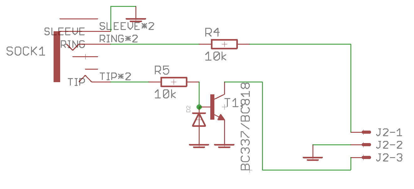
R5 just applies a bit of protection for a CV input (as yet unmapped in software). It's not necessary for running anything. You could also bridge the 3.5mm socket pad to the diode cathode with a resistor.

-
New eurorack modules from midiphy - preview
latigid on commented on Hawkeye's gallery image in Members Gallery
For AOUT? There's an old thread of mine around. Just the AOUT with a different amp design. Dual inverting amp; the first sets the gain/scaling, the second re-inverts and mixes in +5V for bipolar. -
Or did you mean the larger 17x17 BLM? For that one we are working on a new version. All going well it should be available later in the year.
-
SEQ V4+ & Breakout Box - double trigger
latigid on replied to rbv2's topic in Testing/Troubleshooting
Cheers! I'm not 100% sure what you mean with very long lengths. Does it remain when the gate length is set to glide? Video? -
SEQ V4+ & Breakout Box - double trigger
latigid on replied to rbv2's topic in Testing/Troubleshooting
Is the external PSU actually +5/-5V? So a 10V supply? The 0V should be common rather than 0V to -12V. I think that's what your diagram shows, but the 0V of the PSU should connect to the yellowish wire on your diagram, not the black -12V -
SEQ V4+ & Breakout Box - double trigger
latigid on replied to rbv2's topic in Testing/Troubleshooting
Everything sounds correct. Yes and no? Try to have the 0V common to both PSUs, i.e. at the source of the power. -
SEQ V4+ & Breakout Box - double trigger
latigid on replied to rbv2's topic in Testing/Troubleshooting
I repeat my advice from the other thread: Could it be the HW config settings or an issue with midi loops feeding back in? More than one track assigned to AOUT? The perennial IDC cabling issue would also be worth checking. You could also test with _NG again and in MIOS terminal set dout x 1 to check if the problem is replicated. For x you have to count the number of shift register outputss in the chain, starting from 0-7 for the first one. Or simply replace x with 'all'. Check the resistance of your 0V from the Eurorack to somewhere on the SEQ e.g. pin 2 on a MIDI out (the one at 6 o'clock). In the line receiver, is jumper J3 closed? This could cause interference on the +5V line if there are two PSUs fighting. If you use an external PSU you must connect the 0V together with the +/-12V PSU 0V common line. A metal panel is not a good (and some would say unsafe) method of achieving common 0V. I guess you are not using the +5V on the bussboard? But if you are, maybe you don't have +5V connected and the modules are being parasitically powered from the digital signals? (This is not good for CMOS btw.) Did you measure correct +5V on the modules? There is only one "ground" and the separation of analogue/digital 0V is a complex and often misunderstood topic. On AOUT_NG the two are connected underneath the DAC chip; there is no jumper etc. A scope might be useful to see what's going on.