latigid on
-
Posts
2,524 -
Joined
-
Last visited
-
Days Won
149
Content Type
Profiles
Forums
Blogs
Gallery
Everything posted by latigid on
-
Hello, For testing les mecs, you'll want the seq_r.ngc. The easiest place to test for power is on the J14 three-pin connector on the east side of the board. 0V in the middle, +5V above (marked with the silkscreen). Always test that these pins aren't shorted together before applying power. The other pins I've already mentioned I think. The voltages will depend on the speed of your multimeter and would be best viewed with a scope. For 595 chips: pins 16 and 10 = +5V; pin 13 = 0V (resistance may be 10k). For 165 chips: pins 3-6, 10-14, 16 = +5V; pin 15 = 0V. For J89 header, pins 1,2 = 0V, pins 3,4 = +5V,
-
-
-

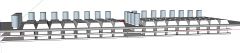
From the album: Mech SEQ
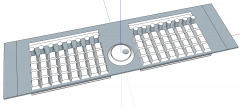
midiphy gate/clocks/triggers module, 4HP -

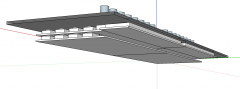
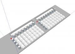
From the album: Mech SEQ
-
Sure thing, it just depends on how many shift registers you have/want, and how the matrix is arranged.
-
Awesome!
-
Maybe I'm overthinking it. I think it would be easiest to specify two separate matrices (16x8, 8x8). If the matrix is 8 rows tall, then I think it should still work to specify the same shift register for the selection pulses. ?? DOUT_MATRIX n=1 rows=8 inverted=0 sr_dout_sel1=1 sr_dout_r1=2 sr_dout_r2=3 led_emu_id_offset=1001 DOUT_MATRIX n=2 rows=8 inverted=0 sr_dout_sel1=1 sr_dout_r1=4 led_emu_id_offset=1129
-
Thanks for the feedback Simon. Annoying as it is, I always restart MIOS Studio after flashing or resetting.
-
Single- or multicolour? You could try with an RGB matrix if it's single (using the other "colours" for extra columns).
-
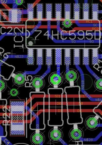
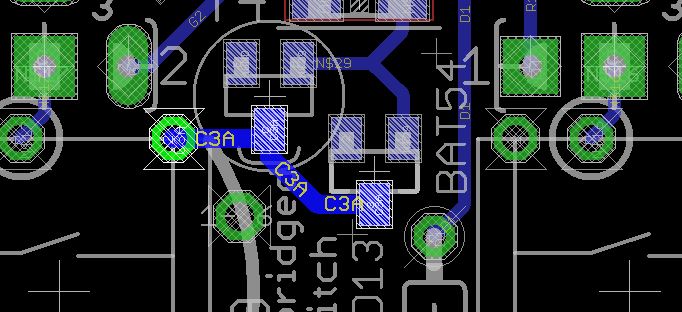
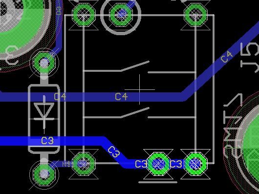
Okay, so just SW17-20 on lemec_L? Let's trace the cathode signal back to IC2. We're looking at the rear of the board. The cathode signal is as shown. It should be common to the same positions on all switches 17-20. After jumping over the bridge (curved silkscreen line) it connects to T4/D13. The issue is likely around this area. The signal continues to R21. Check for continuity between the pads and 0V (ground). The left sides of T4/R21 are intentionally grounded. The signal goes through R3 to pin 4 of IC2. You should be able to measure continuity between the pins of all points of this circuit, with no shorts to 0V unless stated. Test the anode sides (non striped) of diodes situated next to the MEC switches. They should be common with the diode anodes of the same row column, especially seeing that the other switches work. If that helps, please post what the issue was so others can benefit in the future.
-
Hi Pat, When you say switches don't work, I assume that you have loaded the correct .NGC file (left or right) and used set debug on to test if all switches are registering properly?
-
There's an address for FOOTSWITCH in the hardware config file, but nothing for gate. Also, I'm pretty sure there is no routing for this in software, but it would be useful for a future update.
-
 Hi Henry, welcome! We developed the SEQ v4+ with those concerns in mind. It is different to the Wilba project. https://www.midiphy.com/en/shop-details/137/47/midibox-seq-v4-lh-full-essential-kit- On that page you have the full kit available, including the case and hard-to-source parts. There are left- and right-handed cases defined by the position of the JA subassembly. The combined BOM can be copied directly to Mouser's import tool, so it's super easy to get parts. Yes, sometimes Mouser goes out of stock, but many of the parts can be substituted by others (e.g. standard resistors, caps, ICs). Peter also has produced full video tutorials: Best, Andy
 -
Nice!
-
Chiphead (another stereo SID bassline demo :))
latigid on replied to Hawkeye's topic in Songs & Sounds
Don't apologise, it's more than I've done in years! My comment was more of a compliment on how you can get very creative patterns/variations just with a few scene changes using the LoopA.. -
Chiphead (another stereo SID bassline demo :))
latigid on replied to Hawkeye's topic in Songs & Sounds
Who needs automation when you've got two hands and a LoopA? -
In the post above you mentioned putting your fingers on the pads after you replaced ICs. The above statement makes that less clear; I guess you mean on the pads of the switches? Normally the pullup resistor on the 165 input should prevent this. With "less but still there" you mean you still get random triggers in MIOS studio? This suggests that the 165 inputs are still floating (multimeter on the pins should show about +5V), the 165 is damaged or the joints are cold. To me, the board would benefit from reflowing all pads, maybe with a bit more heat, perhaps cleaning the flux off especially around the ICs. The activity matrix (16x8) is controlled by a different circuit on le mec_R. Back to JA, you should be able to "play" the LEDs with the piano roll (set as MIDI channel 3) in MIOS studio if seq_l.ngc is loaded. This might give you a hint if the LEDs are okay but the switches aren't. Other possibilities: cable is poorly assembled, try another and/or check for shorts on the pins. Pins 1/2, 3/4 and 7/8 are connected by design, but there should be no connections between rows. LEDs are not inserted with the correct polarity. Check the pins with a multimeter in diode mode. J89 is the SRIO input, J89A is the output. J89A connects to the next board in the chain, be it le mec_L for a lefty or the line driver for a righty. No problem, just choose the _R.NGC when testing. In fact, I would suggest chaining JA -> le mec_L to see if the SRIO makes it out of the JA. As long as the power rails are okay, nothing else should happen. If le mec works as intended, then at least some of JA is fine. It's normal as we need to shift the serial I/O on pins 5/6 through the registers. It works somewhat like a bucket brigade delay if that makes sense. You're doing great! Keep at it.
-
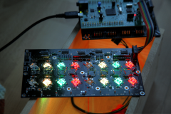
Replacing the ICs also includes RN1? Are digital inputs now working properly (no random messages in MIOS Studio)? Quite a few of the joints look "cold." Did you solder the THT parts from the top or bottom? When you say this results in the picture above? It's not too surprising if so, as the static from your hands can toggle the CMOS gates. That's typically not the best way to control 74HC logic though -- the static can also damage ICs. A picture of the rear would also be helpful. You can try to control the pins directly from the MIOS Studio command line with: set dout z 0|1 where z is from 0-15 on the JA board, 0 is low, 1 is high. Reset the Core, reopen MIOS Studio and don't load an _NGC file. http://wiki.midibox.org/doku.php?id=seqv4plus_jog has the matrix schematic. LEDs will light up if the the Cx column (dout 1 to 7; 0 not used for LEDs) is LOW and the Ay row (dout 10-15) is HIGH. Try not to light up too many columns at once. Note that it's not a proper scan matrix, so can be that multiple LEDs light up at once.
-
Good to hear some issues are fixed! Please check the resistor network on the JA board is the bussed type (15 resistors), not the isolated type (8 resistors). The ICs may have been damaged with backwards cables. Pretty please a picture?
-
Okay. It's normally not an issue here but sometimes the boards benefit from a clean. It may depend on the solder/flux that you use. Do you use lead or lead-free solder?
-
Power issue pulling down the rail?
-
What was the issue with SW-9-12? To test the MECs on SW17-20, like I said, there is no connection unless that switch is inserted (just the marked one). It's the mostly likely explanation. Inserting without soldering might work if the leads scratch through enough of the oxidation that naturally builds up on the through holes and component leads. Or it might not.
-
For the row of MECs SW17-20, you do actually have to solder in the switch that has the "sink bridged by switch" label on the silkscreen. The metal part of the switch provides the connection. For SW9-12 I don't know. Wrong transistor type maybe?
-
If SW1-4 work, then the problem is on the sink side. Check IC2 and associated resistors T3, T4 and the resistors/diodes adjacent. Are all diodes soldered with correct polarity? Please post a picture with your question. It avoids guessing games and is more informative in most cases.
-
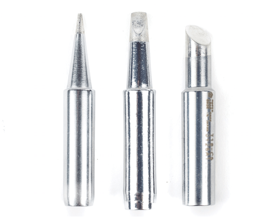
To be clear, I mean one similar to the middle tip of this picture, not the one on the right. It does mean that you have to solder with the iron the same way each time. Maybe my old tip was degraded or my technique wasn't right, but I never could get things going using the very end of the conical tip, rather I had to use the side.