

latigid on
-
Posts
2,524 -
Joined
-
Last visited
-
Days Won
149
Content Type
Profiles
Forums
Blogs
Gallery
Everything posted by latigid on
-
The latest official firmware files are available from http://ucapps.de/mios32_download.html. There is also a thread where "pre-releases" are sometimes available: I would prefer to keep firmware in one location. I added the link to the parent page on midiphy.com, but unfortunately I'm not clever enough to make it clickable. Perhaps Peter can sort it out ;)
-
Recommended cable lengths are given at the end of the BOM here. Did you use the drop-down menu to select a MIDI port? Check all jumper settings and try to use the onboard USB micro to connect to your computer.
-
See http://ucapps.de/mbhp_lcd.html In particular DOGM and DOGL Displays have touch support (with a scanning example), but you will probably need a custom driver. If I remember correctly, TK. is generally not interested in touch screen applications that can be easily taken over e.g. by an iPad or tablet running Lemur and communicating over OSC.
-
Hard to tell! Probably you should replace them, as getting them off will transfer a fair amount of heat to the chip (e.g. if you use hot air rework). I would hope that any damage would be limited to those chips.
-
SRs: JA: 1,2; lemec_L: 3,4; lemec_R: 5,6,7,8,9, so try starting at SR10 for the gates.
-
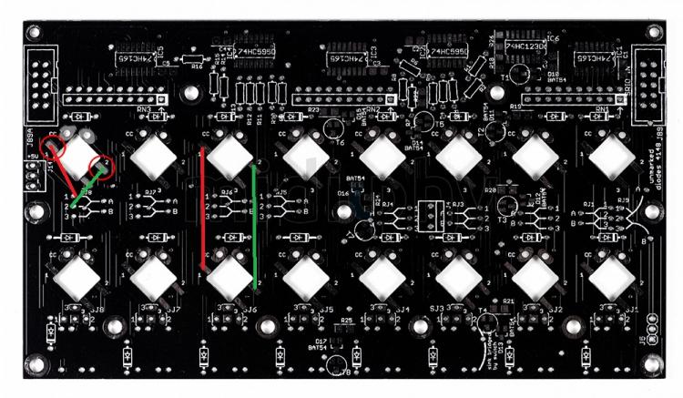
You can verify the connections between the superflux LEDs of the same column. I've attached two examples of how they can be bridged if the connections are broken.
-
Will try when I'm back. I've had success before with alu foil but I didn't have proper keycaps at the time.
-
Fast work! IMO the bleed is okay even without any blocking, and with the blocker it would satisfy 99.9% of users as shown in your image -- even using clear caps. We can always strive for perfection, but the basic goal here is to clearly indicate the state of a step. Given the complexity (and fragility) of the designed piece, I wonder if it's actually an over-engineered solution? Simpler and cheaper would be to use some reflective tape on the topside edges of the Matiases. This is less fancy and more hackish, but might do the trick. As a benefit, you might get a bit of reflection and increase the brightness slightly. This is just my observation/opinion. Don't let me discourage you from building the instrument of your dreams :).
-
Great! I wonder though if it would be better to use a foam (although those go bad after a few years), rubber or other soft material, as we also have to take care of the diodes on the plate PCB? I think a laser cutter/waterjet would be needed though.
-
Wow!
-
Bruno, that's an extremely sexy sequencer! Chapeau! You understand, that we are invested in the clear caps now. But if you would like to try with the small windows, please go ahead. We actually have a set of "relegendable" caps that are intended for the LoopA, so maybe that could accomplish the same thing with a mostly opaque top? Hmm, but the sides would still be clear... One idea I had was to have a plastic "light blocker" part machined from opaque acrylic (e.g. black) and to put that just underneath the keycaps i.e. on top of the plate PCBs. I don't know how much vertical spacing there is for a depressed key, which would determine the thickness of the acrylic. Bruno, would you like to try and cut one? I could send you the DXF for the plate.
-
 You should never connect two power supplies together. If you really need to use two different rails, then the DC sides must be common (connected together) at 0V. I recommend buying the RECOM switching +5V Vreg and using a decent single-rail 9V PSU. @jaytee was the last to do it I think.
 -
This can be done, but now you are splitting the current through the green and blue LEDs. It will be slightly higher through two LEDs than one, but the current passing through each will be lower than if there was just one LED. I don't understand the question: if you have the combo RJs, (red, green+blue), then your colours are red + cyan. Normally the green will be stronger than the blue, so the blue needs a smaller resistor value. Play around with the resistor values to suit your brightness/colour preference. Peter @Hawkeye might have a suggestion as he tried this first. It's got nothing to do with any SJ. Just match the SJ to whatever is on the RJ A buss (red/1). Try on the troubleshooting thread; also as explained above the SJ just connects to the A buss. If you connect an SJ to the B buss, then you have to reconfigure the LEDs in the HWCFG file. Sure, try it and post results! Sure, give it a go. You could connect the battery power to the internal USB micro plug of the Waveshare 407v. Would the battery packs sense an external charge from the normal SEQ v4+ USB B plug and charge that way? Not sure... You could wire the +5V on the wCore (e.g. the micromatch connector) to an SPDT with one side to the battery and the other to the USB breakout PCB. Do you intend to connect through USB to a computer etc.? If not, why not just plug the power bank into the USB B?
-
Hello, Don't worry about it! The only thing that might be damaged are the ICs (74HCT125 x2 and 74HC595). You will easily see if these are bad though, as the displays won't initialise (595 chip) or the SRIO chain doesn't work (IC1B). If you weren't applying heat directly to the ICs though, I think they should still be fine. Try and see! If there's an issue, it might be wise to invest in a hot air gun to swap the ICs, which ironically would be really nice for popping out pinheaders too :).
-
Looks like the LPK25 can be battery powered as well? I don't have any experience with this device sorry, so I can't help you there. The current case revision should have correctly positioned cutouts to support the edges of the MIDI8 board. It's not possible to use the central mounting points as these would conflict with the rack version/blind plate metal. Older cases could be drilled out if really required.
-
MIOS Studio upload of SammichSID app fails with Error #11 at 99%
latigid on replied to Road_Kill1019's topic in MIDIbox SID
Nice job! Sending good vibes over from Moab. -
MIOS8/32 repositories now hosted at Github
latigid on replied to TK.'s topic in MIOS programming (C)
It's a nice idea, though SVN was still fine for a passive user like me. This was discussed elsewhere, but just to be clear: you (TK.) prefer to keep control of the master line and review all changes, and you will keep the same license terms as non-commercial for personal use only (no GPL/CC-BY etc.)? This is not a request for you to change anything you don't want to of course. -
+1, remove the plastic part if possible and just go one pin at a time. Normally you can get a flat tool or blade underneath and the plastic part should lift out. By gold pinheaders, do you mean shrouded headers? If you don't have replacement parts available, normal unshrouded pinheaders also work (I normally use those and check the orientation carefully before connecting IDC cables.
-
MIOS Studio upload of SammichSID app fails with Error #11 at 99%
latigid on replied to Road_Kill1019's topic in MIDIbox SID
Welcome! Do you get any "READY." message on the LCD (tweak the contrast/brightness) before flashing? This might help. I don't have any ideas on why an upload would go to 99% and then fail though, so perhaps if you had the LCD running you might see the program correctly installed? -
Could be your MIDI interface (check the blacklist on the wiki? Do you have the MIDI circuit installed, including the optocoupler chips? Photos?
-
Hello, OTG works with some things and not so well with the others. First to check the power jumper on the USB board is stuffed? Note: this is a very basic spec for OTG (no overcurrent regulator etc.). So please be sure that you know what you're doing!
-
@Menzman Great job! Displays look perfect!
-
@gbrandt It should be possible to swap the RJs from 1:3 even without disassembly. But you've probably used position 1 for SJs, meaning if you don't use the red LED, the MEC switches will also need to go to the same position as was done for the red. For RJs, 1 = red, 2 = green, 3 = blue. For easiest hardware mapping, the MEC SJ should always be the same number for whichever RJ1|2|3 -> A. The least work might be to desolder the RJ A->1 resistor and cross the [new] resistor over the top of the "B -> 2" resistor, so A -> 3. Then on the SJs, swap the resistor from 1 to 3. This would keep the hardware mapping the same. To do a tidy job and make A -> 2, B -> 3, the LED colour functions will be inverted as you see at the moment, but I think you can swap them in software. For completeness, if you do the tidy job method, then the SJ should connect to #2 for all MECs.
-
Congrats! Did you go for the green/red or green/blue? Best, Andy
-
Well spotted! Note that the LED cathodes are common with some switches, thus you may falsely register switch presses

