

latigid on
-
Posts
2,524 -
Joined
-
Last visited
-
Days Won
149
Content Type
Profiles
Forums
Blogs
Gallery
Everything posted by latigid on
-
If you essentially trigger the encoder pins with the plate PCB disconnected and there is no spurious matrix event, then I agree that there is a short somewhere on the plate board. It is really puzzling that you don't see any short to J2 from the encoder. Check again that all RNs are cut flush, even with stacking headers maybe the pins are too long? The encplate PCB is fairly simple and just connects the encoders to J1/3 and the diode columns to J2.
-
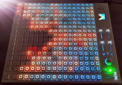
I still think if you have a short between the encoder pins and J2, pin 6, that would probably explain your issue. Try shorting J1 pins 8/9 to 0V, (not 10). That's where that encoder ends up. You should see DIN events corresponding to the encoder if SEQ_L/R is loaded. See if enabling the DIN matrix brings back the LED storm too. Another weird thing that sometimes happens is that your MEC switches have broken LEDs.
-
 It would be perfect for "Snake II"! Thumbstick to change the direction.
 -
hw_id=36 means that it is the 36th DIN input. I think the DINs are counted backwards, so that corresponds to IC3, pin 14. That pin is connected in parallel to J2, pin 6 and RN2, pin 5, along with the diode anodes of that column. (If they are counted forwards, then it is IC3 pin 3 and J2/RN2 pin 7 and the 5th column of diodes.) Logically, the only way that you can trigger that DIN pin by turning EN4 is if there is some connection between the encoder pins and that pin. It could also be the diodes in the 4th column of switches. With the plate board connected, see if you get any shorts between the encoder legs and all pins of J2. Disconnect the plate and try the same debug test by shorting J1 pins 9/10 to 0V. If you get the same hw_id=36, then your issue is on lemec_R. If the issue disappears when disconnecting, then there is some unintentional contact made when stacking the boards together.
-
Very tricky! To check: it does the same thing if you change the the sequence of boards and load the respective .NGC _R / _L? You could try to modify the .NGC file by commenting out the DIN matrix DOUT_MATRIX n=1 rows=8 inverted_sel=1 inverted_row=1 sr_dout_sel1=3 sr_dout_r1=4 led_emu_id_offset=1001 DIN_MATRIX n=1 rows=8 inverted_sel=1 inverted_row=0 sr_dout_sel1=3 sr_din1=3 button_emu_id_offset=1001 That might help to narrow down where to look.
-
Yes, that is the right idea with the HWCFG. LG, Andy
-
That I am not sure of. There are also unused functions e.g. the footswitch and gate. It would be possible to remap any button without recoding by assigning it in the HWCFG. But I am not sure what function to put on the datawheel. I think I once asked if it could be an enter key or similar but I am not sure where/how that makes sense.
-
Hi Tim, It's an interesting idea for sure! IMO the midiphy front panel would better suit your needs as you have more direct feeling for what is going on (16 direct tracks, haptic memory of the 8 buttons for selection row changes). Not so useful are all of the LED indicators... As for potential mods, there is certainly scope to do this. For something totally non-invasive, you could consider using the DB-25 expansion port and rewriting an SPI driver in place of the analogue out module? Not sure how feasible it is, but you could also use the USB host if you can write a driver for a USB connected device? I was actually thinking of something like a braille display that mirrors/converts the text on the screens somehow? You might also be able to either replace the I2C MIDI module with something or use the spare I2C bus. Best, Andy
-
DnB beats always appreciated :)
-
My apologies, that would be R14/R15 to IC4. Also check if any of R9-R16 are shorted to the adjacent resistor (the pins closer to the 595 would also indicate shorts on the IC pins).
-
Find a spot to clip your 0V lead e.g. the middle pin of the slide switch on the USB board, or solder a wire to the middle pin of the power headers there. Then just go through point to point, measure on the chips, the RJs etc. BTW, does fluxtest.NGR run properly?
-
Just to ask the obvious: are your resistor networks soldered on the right way? As you have a working lemec_L board, you can probe around for voltages and see where things differ. The parts that drive the fourth column of LEDs are: Matrix column RJ4/ RJ8, T15/16 (front side), R24/R25, IC4 pins 1/15. If the rest of the LEDs in the rows work, then there is no issue with the sink sides of the matrix.
-
Not easy to debug sorry... Basically there is no reason that you should get matrix DIN toggle events when rotating an encoder. There might be some sort of unintentional short between the boards (e.g. from a diode and you push the encoder button?). IC3 is the shift register responsible for the input side of the matrix, so maybe run the hot air around there or consider replacing that chip? The associated pull up/RN is right next to it
-
For example at Schaeffer (Front Panel Express): You would need to design a stepped window but it can be done! Maybe there is a design file around. Another way is just to use a thin sheet of whatever colour, either with or without a clear window. But if your panel is thick, a nice window looks subjectively better.
-
What output do you get from MIOS Studio with "set debug on"? The encoders are directly connected to 165 inputs, so IC4 is not involved here. Looks like there are a lot of blobs around IC3? Encoder pins connect to Plate J1, pins 8 and 9, if that helps. The encoder shouldn't hit anything below it, but you could try to slip a piece of card in between the boards to rule out unintentional short circuits. R13 does go to pin 3 of that IC. But make sure that it doesn't connect anywhere else.
-
You could use a white OLED (or LCD...) and a red acrylic screen protector.
-
That's right! Not sure exactly what your issue is here, but if you've narrowed it down to pin 13, IC5, you could bodge wire it to pin 3 on J5? Pin 1 of the connector has a square pad.
-
Clean work, you're doing great! That is a via that brings the SR signal to the transistor.
-
Thanks, it works. Can't see anything obvious. You can check the components I mentioned before. It could also be a too-long resistor leg, also on RJs? Before desoldering all of the switches, you might try to remove those resistors.
-
What I meant was to desolder a potential bridge there. Generally you don't want the output shorted to the power supply. But a constant voltage here would mean that the transistor base was always in the high state and not able to switch as required with the 595 pulses. I guess that's the case... light|shields and keycaps can stay on!
-
I could not see your picture of the soldering As the behaviour is common to a column (two columns, but they are only separated by RJ4/8) it is probably caused by 1. Wrong transistor type or otherwise an error with T16. Yep, that's on the top side of lemec_L! 2. The pin driving T16, so R16 and IC4, pin 15. With luck you just have a solder bridge to +5V (pin 16). Good luck!
-
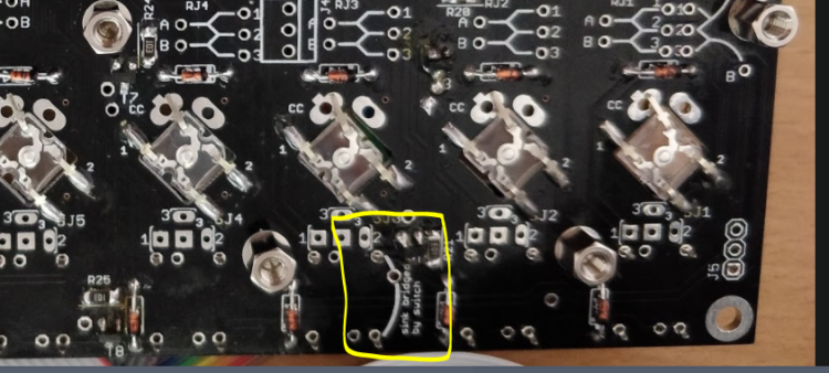
Nice! Just be certain to solder the LED anode in the encircled pin, maybe test before soldering. It sucks to remove them if they are the wrong way around! But you probably already know this joy from the JA PCB.
-
Also a good catch, I had forgotten about that! There is not much risk in soldering in the MEC switches. It is only the Matias switches that you really want to be sure about because once they go in you have to desolder all of them to get to the inside of the PCB stacks (BC808s).
-
The switches SW17/18/20 won't work in the matrix unless this is bridged, actually done by the switch SW19 itself. Try to insert a MEC switch here. Sometimes it will work without soldering, sometimes you need to solder it in (or otherwise bridge it) to get a signal.
-
The 3M headers seemed to be easy to source and typically had good stock. It is also less effort to keep track of one part series. The 6mm "standard" single-row header might work (see above post) but the extra fractions of a mm help. That is why the 8.08mm part was ordered. Feel free to stick with 8mm. The same TE part on Mouser/Digikey is discontinued. Remember that the TE part you found has a plastic base height of 2.8mm, whereas the 3M one is "only" 2.54. So already there is a difference of 1mm.

