latigid on
-
Posts
2,524 -
Joined
-
Last visited
-
Days Won
149
Content Type
Profiles
Forums
Blogs
Gallery
Everything posted by latigid on
-
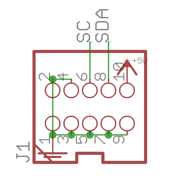
Right, that would short circuit the +5V rail to 0V!
-
So everything else works when the I2C board is disconnected? Is the cable still plugged in here? Do you measure a short circuit on the I2C board? Measure across a 100n capacitor, or what voltage do you read? Are your PICs in the right way around? How is the soldering around J1/J4A? Please upload a photo of the board to check. To check if it's the PICs, you can try to remove them and see if you get the same behaviour. Best, Andy

-
 Hi Ewen, Could be possible, but of course you need to redefine the ports in software, also to handle the incoming events appropriately. Does it not work simply to extend the J89 SRIO line? If it needs to be remote in theory you could also put a line driver at the end. Or, can't you just send in the DIN inputs to the boards? They could also be distant from the chain. Best, Andy
 -
i made a video (and cut it - in real it was twice long...)- that explains the whole thing - and why a delay - i think is needet: The "realtime switch" makes more sense now. I thought you meant you had 8 individual switches to pick the core directly. delay? If it's controlled by the counter, then I think only one line can be activated at once. I don't think you really need the delay lines. If the run state chosen by the counter is fed to the Core, when the state changes you could run a wait timer to ignore incoming inputs, also to delay sending more data out. i dont get this idea. A 595 shift register has 8 outputs, so in theory you can write a program to choose the output instead of cycling through the counter. I think you need to buffer/switch them, otherwise the clock lines etc. will interfere?
-
I didn't check in great detail but that seems to be the right idea. The delay part didn't really make sense to me. I think that you also need to consider how to avoid activating >1 line at once. As an alternative idea, why not program a 595 shift register to send out the required "single" signal? You could easily scan in switches (momentary buttons) to specify the active line and output one 0/LO out of 8 outputs. You could also have a cycle button. Note that outputs are high impedance (i.e. disconnected/floating) when the /OE signal is high. This means that you must define the logic level of all downstream logic inputs with pull-up/-down resistors (1k-10k), whatever the default state should be.
-
Troubleshooting Wilba hardware or SEQv4+ software bug
latigid on replied to workspace's topic in MIDIbox SEQ
Very nice! I really wonder what happened to those 595s? Could it be oxidation on the sockets? For ports, I think we will stick to the 8x MIDI outs currently available. I know Peter controls over 30 synths by using Thru splitters and that works just fine too. But as another idea, you could always repurpose the old SEQ as a glorified router? Best, Andy -
Troubleshooting Wilba hardware or SEQv4+ software bug
latigid on replied to workspace's topic in MIDIbox SEQ
Grüssi Michael, I would suggest to first check the tactile switches as these often go bad. I would highly doubt a software error, but I tried it on mine and couldn't replicate your error. Just the switches were bad and needed extra effort to push. The only other thing might be a bad diode or LED, but I would think that that's really unlikely. Best, Andy -
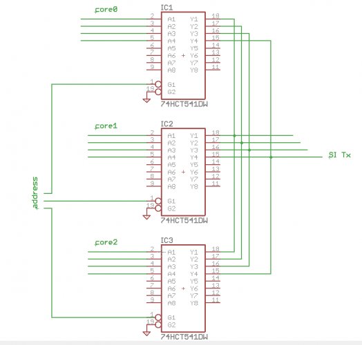
Okay, all good then! Above schematic is wrong of course as the "SI" pin from the chain should be connected to the input! But you get the idea I hope. Actually, the SI normally comes in unbuffered and only SC/SO/RC1/RC2 (outputs) are buffered. But for your case I think you also need to "switch" the SI? So you can use 5 gates or just combine RC1/RC2 as they are normally set simultaneously
-
It's not quite clear to me what you want to do? You want to have one J89 SRIO chain and switch between several Cores? If that's right, it is trivial to make a Johnson counter/decade counter out of a 4017 chip. You could think to use the output enable pin(s) of the buffer (541 or 125) that is used to interface the buss to the core. Each Core gets one buffer with the datalines connected to the inputs (+DIN to an output), the outputs are common to the J89 chain (+ the serial in). Advance the counter to "turn on" one chip.
-
We can track the SEQ v4+ serial numbers here: https://forum.midiphy.com/d/60-midiphy-seq-v4-official-serial-number-thread/2
-
No worries! Glad you could find some!
-
I get the same, but one trick is to highlight the entire contents and "print" the page to PDF. Then you should get the images in line. Best, Andy
-
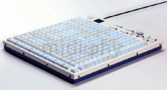
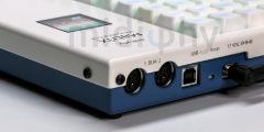
This one has been a long time coming but today we're ready to release MatriX. It has a similar form to the BLM16x16+X but now with mechanical keyswitches and full RGB backlighting as well as a joystick and OLED display. Peter has done a great job in reprogramming the 32-bit application, in particular to extend the LoopA. Check out some features in the video below! Essential kits are available here: https://www.midiphy.com/en/matrix/ Have fun building! Andy
- 2 replies
-
- 1
-

-
- midiphy matrix
- midibox blm
- (and 1 more)
-
-
-

From the album: midiphy MatriX
© 2021 latigid on
-
From the album: midiphy MatriX
© 2021 latigid on
-
From the album: midiphy MatriX
© 2021 latigid on
-

From the album: midiphy MatriX
© 2021 latigid on
-
Very cool work Rolf!
-
Hello, The answer is "maybe": Looks like you'll need to compile the code and run it on iPad somehow. No idea how to do it! MiOS Studio is just a USB interface really. Mostly for uploading firmware or monitoring. The sequencer application as pre-compiled firmware runs on microcontrollers only.
-
I'm not too savvy with buss control or loopbacks, but from what I saw I don't think it's possible to have two busses controlling one track. (Also I think 4 busses are the limit too.) Would it be an option to have your MIDI notes set up on different patterns? Maybe you can trigger a pattern change with your drum hit and that alters something? Btw. how do you trigger step advance manually? I saw that the divider can be switched to manual, but isn't it a CC that then controls the track progression? Or am I missing something?
-
We're using this for midiphy SEQ v4+ https://www.mouser.de/ProductDetail/Bourns/4610X-101-103LF?qs=%2BG4UmwsSIwOIq1qGQ3k3nQ== Maybe you can find an alternative? You can also jury-rig bussed SIP resistor networks by mounting individual THT parts vertically and connecting the common ends together:
- 1 reply
-
- 1
-

-
Could be! Also please check the clearance in the case. The OLEDs we supply are thin (y dimension) enough to fit but there is not a lot of room. I think some models of display simply won't fit in the case.
-
Welcome! The midiphy PCBs also have a standard IDC, so that means you can mount the PCB anywhere and use a ribbon cable to a breakout DB-25 anywhere on the case, if that suits better.
-
Hello and welcome back! We have Eurorack-format modules here (including a "Euroceiver" board): https://www.midiphy.com/en/shop/188/MIDIbox-Sequencer-v4+-Eurorack-Modules and the line drivers in question: https://www.midiphy.com/en/shop-details/0/10/linerx-pcb- https://www.midiphy.com/en/shop-details/0/9/linetx-pcb- Best regards, Andy