

latigid on
-
Posts
2,524 -
Joined
-
Last visited
-
Days Won
149
Content Type
Profiles
Forums
Blogs
Gallery
Everything posted by latigid on
-

LoopA V2 Introduction, Features & Support Thread
latigid on replied to Hawkeye's topic in MIDIbox User Projects
Were the CN3 jumpers removed from the DISCO board? Otherwise the SWD programmer is connected to two STM32F4 chips. To my knowledge the circuit shown is correct but it has been a few years since I tried it. -
LoopA V2 Introduction, Features & Support Thread
latigid on replied to Hawkeye's topic in MIDIbox User Projects
Connecting over JTAG might be a good try. You'll find some documentation for that on the wiki, especially flashing with an ST-LINK/DISCO board http://www.midibox.org/dokuwiki/doku.php?id=wcore -
If you think an available commercial device can fulfil your needs, then get one! DIY is a different thing. It is potentially more expensive and you have to put in the tools and effort to finish things, but the journey can be very rewarding and sometimes you can obtain tools that are not found elsewhere, often for the very reason that they would be impractical or uneconomical to produce in scale.
-
CV1 - ControlVoltage-ENV, LFO, MSQ and Sampler
latigid on replied to Phatline's topic in MIDIbox User Projects
Looks really great! Depending on the width and power draw of the modules, you might want a few more bussboards/PSUs. See how you go! Best, Andy -
Well done! Are you building the CS too or somethin else?
-
Sorry, the extent to which I could help is already in the posts above. If you have more specific questions there might be others who are more into code modification. But at the moment it is hard to know what step you are on. It sounds to me like you are stuck right at the beginning, and I think it is rather up to you to learn how to modify the code to get what you want out of it.
-
Hi Frederik, Yes, most ports with specific functions can be used in parallel. J8/9 is for SRIO i.e. input/output shift registers that chain in parallel (DIN/DOUT) J19 is for SPI with two chip selects (AINSER/AOUT) etc. Check the STM32F4 Core details The SRIO chain extends in series parallel, no need for additional Cores generally. Regards, Andy
-
https://github.com/midibox/mios32/blob/master/mios32/STM32F4xx/mios32_ain.c https://github.com/midibox/mios32/blob/master/modules/ainser/ainser.c https://github.com/midibox/mios32/tree/master/modules/aout Basic drivers/assignments: https://github.com/midibox/mios32/blob/master/mios32/STM32F4xx/mios32_spi.c https://github.com/midibox/mios32/blob/master/mios32/STM32F4xx/mios32_iic.c Maybe it would be easier for you to use the Arduino and output an analogue voltage to be read by the STM32F4 AIN? That way you can use your working system without much extra coding effort. MBIO supports AIN either on the MCU ports J5A/B or using the AINSER module (typically less noise on the signal).
-
As far as I know, there are no I2C peripherals that were coded into MIOS32. The closest thing that I am familiar with is the I2C MIDI modules, that according to TK. were not trivial to code for, and at that on very low-performance 16F PIC chips. All the MBHP framework gives you is a hardware port on the MCU. You could consider to compare your arduino sketch with a device running off an STM32F4 chip or similar. Alternatively, you might find more code examples of SPI devices. Maybe you can try to code a driver for a similar sensor with an SPI interface? The uCapps project is here: http://ucapps.de/midio128.html -- it is more targeted towards general users who would like to use the project without writing code for it. The git project is here: https://github.com/midibox/mios32/tree/master/apps/controllers/midio128_v3 You would need to modify the code to suit your needs. Note that the code is written in C, not python. You can find the documented functions and some examples here: http://www.midibox.org/mios32/manual http://ucapps.de/mios32_c.html Best of luck to you if you decide to follow this journey. Others will probably not write the software for you, but if you post your modifications and explain where you are having difficulty, some might be able to help.
-
LoopA V2 Introduction, Features & Support Thread
latigid on replied to Hawkeye's topic in MIDIbox User Projects
Well done Matt! Enjoy your LoopA! -
You need to define your question better. You are using some sort of sensor, but have you written a driver for it to be used with MIOS? How would you expect the velocity values to be modified? Have you looked into the MBIO code?
-
LoopA V2 Introduction, Features & Support Thread
latigid on replied to Hawkeye's topic in MIDIbox User Projects
Hi Matt, wonder if it is a short circuit to 0V (ground) somewhere. Test each board in turn for shorts on the +5V line. Easiest is across any 100nF cap. Did you solder in the Matias switches yet? Sounds like it is on the Base or Plate PCB? Please upload sharp photos of the PCBs. Some status LED illumination is expected if the audio jacks and PCB stack are disconnected. Best, Andy -
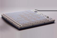 Thanks! MatriX has some similarities to the BLM16x16+X in that it has 17x17 keys and a few sliders, and communicates over the same MIDI protocol. Apart from those it is really quite different! The BLM protocol has a "keyboard mode" where you can play with different velocity on the y axis, notes (usually forced to scale) on x. Best, Andy
 -
Well done to #42! Is it the answer to the question "what is the meaning of life, the universe and everything?"
-
Hi! Great, we want to see the image (and give you a serial number)! There is a 2MiB size limit, so please try to reduce the size with an image program and save as jpeg or png, should work then!
-
I have only seen it once in person, but it is an incredible and really solid device.
-
Both nice units! And thanks for your kind feedback and nice summary. Congrats to #41 !
-
Cool! I think here you will have an easier time wiring up and figuring out things hands-on. Please feel free to post your progress. Best of luck! Andy
-
No problem, hope it's helpful! You will need to figure out the wiring puzzle. The following links might be of use: http://ucapps.de/midibox_ng_manual_ngc.html -> search "LED_MATRIX" and "DOUT_MATRIX" There you can understand how things will look in software. http://ucapps.de/mbhp/mbhp_dout_8x8leds.pdf http://ucapps.de/mbhp/mbhp_dout_8x16leds.pdf http://www.midibox.org/dokuwiki/lib/exe/fetch.php?media=home:users:ilmenator:rgb-led:midibox_rgb-led_matrix_8x8_v1.3_schematic.pdf https://github.com/midibox/mios32/blob/master/apps/controllers/midibox_ng_v1/cfg/tests/blm16x4.ngc DOUT_MATRIX n=1 rows=4 inverted=0 sr_dout_sel1=1 sr_dout_r1=2 sr_dout_g1=3 This is an .NGC example of one four-row matrix. In theory you could share the same sr_dout_sel1=1, though you still need dedicated RGB columns. As you have common-anode LEDS: inverted_sel=1 and (optionally) inverted_row=1 commands should be used when defining the matrix. This: https://www.sparkfun.com/products/10680 ? You don't need that if you will use DOUTX4 PCBs. You can get creative with how you assemble IDC cables, no need to follow the original order or total number of conductors. I guess you could consider defining an 8-row matrix? If you save one shift register but give yourself a wiring headache, maybe the simpler approach is better. See ilmenator's approach for an 8x8 RGB matrix.
-
Nice choice of switch footprint ;-)
-
Still not totally easy to follow but I get more where you're coming from. I would prefer to draw it out as a logical table rather than a netlist. Are the LEDs on boards and you want to use DOUTX4 PCBs to drive them? Or are the shift registers also on your LED boards? 4x source rows as selection pulses will work, though you get no faster multiplexing as that's limited to a doubled 4x pattern. But colours can only be 16 columns wide. If using DOUTs, you could buss two IDC10 ribbon cables and define them as one matrix but you still need a second DOUT to drive the 'second' matrix (third LED board). I would suggest simply to use 3x DOUTX4 boards and define three separate matrices with 4x source rows each.
-
Of course matrices of 16 rows/columns are also okay but don't relate to what is requested here.
-
MB_NG supports multiple matrices. You just need to define the shift register where each block of 8 is connected. If any block is less than 8 wide, no problem. It will just take more shift register chips to address them. Best idea is to draw a circuit diagram of how the LEDs are arranged. Then for each contiguous block, that is one shift register with a maximum of 8 rows or columns. You probably need sink transistors (NPN) on the rows unless your current draw is low. Please keep posts public so other travellers can benefit from any knowledge or lessons.
-
You can create a matrix with 9x rows (sink side) and 8x3 columns (R/G/B source sides). So you need 5x 74HC595 chips because they only have 8x outputs. You also have 7x rows spare as it is a 16x8(x3) matrix. If you have buttons you can connect 1x DIN 74HC165 chip to the columns with diodes to the switch inputs.
-
Gewinde = thread/threaded Apparently called a cube standoff or mounting cube e.g. https://www.newark.com/ettinger/05-60-233/spacer-m3-12mm-x-6mm-brass-nickel/dp/59M4072 Gewindeblock: https://www.ettinger.de/p/montageblock-6x6x12mm/005.60.233
