latigid on
-
Posts
2,524 -
Joined
-
Last visited
-
Days Won
149
Content Type
Profiles
Forums
Blogs
Gallery
Everything posted by latigid on
-
There are two types of SMT resistor networks in the SEQ v4+. The bussed one on the JA board and two isolated on lemec_R to serve as current limiting for the activity matrix. Just use the product page to make sure you're ordering 8x resistors in a 16-pin package. If there are 15 resistors, that's the bussed one. (Seems like your RS part is good.) (There are also bussed THT arrays on lemec boards) For the pin headers, even normal length ones could work but they tend not to make good enough contact. Adding up the thicknesses: connector 5mm PCB 1.6mm inter-PCB spacing 3mm - plastic thickness 2.8mm 6.8mm of pin So I would suggest 826630, or actually 826935 as it matches the tin plating better. The 8mm one that you found would probably still work, just be aware that if it sticks through the header too much, it might contact the case.
-
I just hope that it wasn't 3x BAT54 on top of each transistor ;-) This approach works best I found when the solder has burned through its flux. If it's too hard, you could consider a fleck of copper tape or a strand of wire.
-
For v1.3_R Omit: IC6 (74HC123) C6 (or leave it in, no difference) C7 (top side) R17 (top side) Stuff: R26 (1-10k) or bridge it.
-
You will probably get bad ghosting without the BAT54s. Short of ordering a new board, just "stack" the BAT54s 1:1 on top of the BC818s, so with the text still facing up for both transistor and diode. Please stuff R17 (any value up to 10k) or simply bridge it. C6 and the nearby diode can be left unpopulated.
-
Awesome work!
-
No need to replace that pad, pin 1 does not connect to anything. Best, Andy
-
Yup, that's a common one! Actually Peter shows you the Mouser part number in the video but of course it is not 100% obvious and the part numbers are fairly similar. If you used leaded solder, you should be able to remove it easily. Flux can help but it is not 100% necessary. Normally I try for about 300°C and a relatively high airflow for this. If you need higher temperature it will probably be okay for the RN, but you'll need to take care of the other chips, MEC switches and encoder. When removing the chip, you might need to wiggle it to get the solder moving. When I do it, I always try to slide the chip laterally along the leads i.e. towards/along the long sides of the pads. This tends to keep the PCB pads intact and doesn't bend the chip leads, hopefully also the leads don't get too messy with solder blobs. When done, if necessary clean up the PCB pads with flux/braid to make the surface flat again. If necessary do the same with the chip. If it's not possible to easily get things flat, you can add flux and use the reflow hot air station again. Good luck!
-
You can get plugs of this form that have solder pins, but maybe you want to hack one together with a normal IDC (ribbon) plug? Take an IDC and remove the crimping part, then bridge all of the pins required, except leave the supply voltage (or 0V) floating to avoid shorting the power supply. Or take a ribbon cable and do the same? Just leave one conductor free.
-
Nice track!
-
Hehe! Yes, plenty more than 44 sold but some people are not aware that this thread (or even this forum!) exists.
-
Haha! Honestly I had the PCBs built for a while but never found the time to put everything together. I had to test a PCB revision anyway so though it was a good opportunity.
-
Took a while! I didn't have enough of one LED colour so it is multicoloured
-
Awesome! Glad that you could get to the bottom of it and that the caps didn't explode too violently!
-
Congrats #43 ! Looks great in the rack!
-
Yes! Just switch the jumper appropriately.
-
Hi Laurent, For euroceiver versions 1.5 or older there is a J0 jumper above J19, near the USB. There is a jumper on the line transmit board but it basically supplies power over the DB cable, which you don't really want as there is a big voltage drop. If grounding is not the issue then I would typically expect power supply (e.g. noisy USB), bad cabling or similar. At least you can test directly without the line drivers now the SEQ is open. Best, Andy
-
It is important with older euroceiver boards that the J0 jumper is installed. This grounds the two systems. Is yours grounded? To rule out the line drivers, you can bypass them but you'd have to open the SEQ case of course... Something else to try would be a different power supply e.g. the USB+5V instead of the regulator etc. Best, Andy
-
That pad (pad 3) is not connected, so you can ignore it!
-
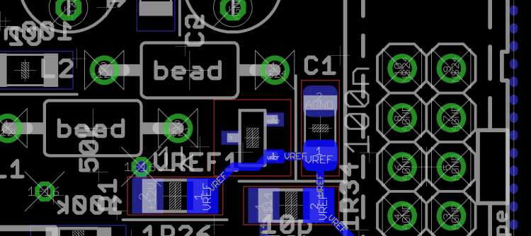
Where is the trace lifted? Attached is a layout snippet that I hope could help.
-
Hello, Not sure sorry... But you should be able to interrupt the J8/9 header with your module. Best, Andy
-

LoopA V2 Introduction, Features & Support Thread
latigid on replied to Hawkeye's topic in MIDIbox User Projects
It should press fit but Peter has a technique to use Scotch tape to hold it in place before lowering the case. For me, I slightly roughen the back powder coating (say 120-grit sandpaper) and apply drops of superglue to the corners, away from the edge. Then I carefully place the protector in. If you mess this up though, you'll get a nasty smear on the plastic, so tape is probably safer and sufficient. -
LoopA V2 Introduction, Features & Support Thread
latigid on replied to Hawkeye's topic in MIDIbox User Projects
Excellent job! Regarding the light|shield/standoff collision, I had the same experience but like you say, it is simple to just cut out a little bit. I also found that it was useful to cut out a bit of the waveshare JTAG header (the side near the crystal) to avoid collisions with the THT resistors on the back of the base PCB. -
LoopA V2 Introduction, Features & Support Thread
latigid on replied to Hawkeye's topic in MIDIbox User Projects
We have seen a case where trying to flash with the PA0 port left floating could lead to a corrupted bootloader. Hence the resistors R101 and R102 seem to be very important (that were not installed on your initial build). The footswitch/gate LEDs are driven by the buffer chip IC6, so it is expected that they don't illuminate with no inputs. Anyway, great that it seems to work well! -
LoopA V2 Introduction, Features & Support Thread
latigid on replied to Hawkeye's topic in MIDIbox User Projects
-
LoopA V2 Introduction, Features & Support Thread
latigid on replied to Hawkeye's topic in MIDIbox User Projects
Restart MIOS Studio?