latigid on
-
Posts
2,524 -
Joined
-
Last visited
-
Days Won
149
Content Type
Profiles
Forums
Blogs
Gallery
Everything posted by latigid on
-
What did you have in mind? If you want, you could assign it to any function in the HWCFG SR Pin 1/7* 6 *1 for LH, 7 for RH There is a Moog v-trig converter on there, so a positive gate at the tip of the jack should pull the 165 pin low and enact a DIN event. How about clocking in an analogue tap tempo? The 3.5mm ring is connected via resistor R4 (USB PCB) to SR pin 5. Probably the 10k value is too high, rather go for 4k7 or less (e.g 1k/2k2). So shorting the ring to 0V will trigger a DIN event there. And a post from 2011 illuminates the actual intention: So: # SR Pin BUTTON_FOOTSWITCH 1 5 or for RH # SR Pin BUTTON_FOOTSWITCH 7 5 Please test it if it sounds useful! Best, Andy
-
Good job!
-

LoopA V2 Introduction, Features & Support Thread
latigid on replied to Hawkeye's topic in MIDIbox User Projects
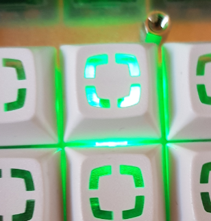
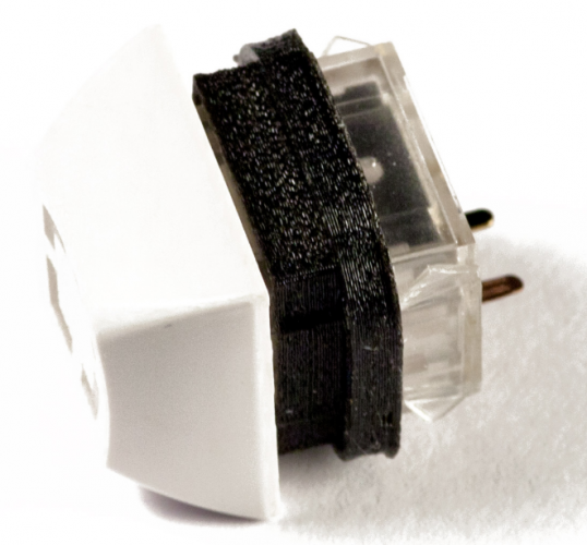
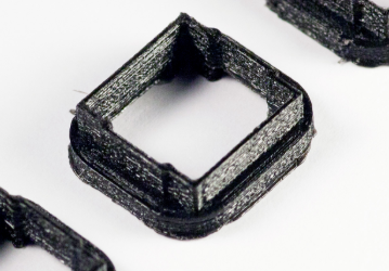
Thanks for the feedback and ideas! We know there is a bit of LED stray light going on. Some people like it as it reminds them of their backlit mechanical keyboards. But for indicator LEDs it can be suboptimal. For the smaller 2x3x4/2x5x7 LEDs, a good technique we found was to use a piece of heatshrink tube. It's a great idea to roughen the top too if that is preferred. Sometimes you can also make the LED cloudy e.g. with acetone (nail polish remover) but needs to be tested. For blocking the light from adjacent Matias switches, we have another solution in the pipeline (more info soon)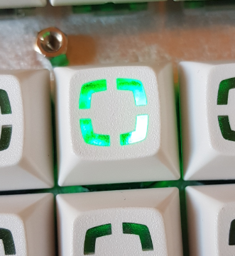
-
Never heard of DFU. SWD (or JTAG) is more common.
-
Try it! Report if it works. Possible but would take much more effort.
-
LoopA V2 Introduction, Features & Support Thread
latigid on replied to Hawkeye's topic in MIDIbox User Projects
@keelhauler that's super cute! We do try to make designs cat-friendly :) -
LoopA V2 Introduction, Features & Support Thread
latigid on replied to Hawkeye's topic in MIDIbox User Projects
Awesome! Thanks for the positive and informative debug reports and have fun with the LoopA :-). -
LoopA V2 Introduction, Features & Support Thread
latigid on replied to Hawkeye's topic in MIDIbox User Projects
Glad that the OLED issue is solved! Could I ask where/how the broken trace originated? For the DIN problem, you can recheck the soldering on Core IC1B especially pin 13 (RC2). Make sure that you get contact all the way through the header when the sandwich is assembled. Please reflow the joints to get "volcanoes" rather than "balls". You will have to be careful not to move the individual pins around because the plastic part that normally holds them together is gone. My approach to soldering the J89 pin header is different to Peter's. I found that you don't have to push the pins all the way to the bottom of the corresponding socket on the Core and there is no need to remove the plastic. The plastic prevents solder flowing through the holes and making blobs that might short out other pins. ----- if you have any spare 2.54mm pin sockets you can use this temporarily on the long end to hold them together. On the Plate PCB can you provide the part number of the resistor networks? If it is an isolated type the DINs will not work. The orientation is also important.
-
LoopA V2 Introduction, Features & Support Thread
latigid on replied to Hawkeye's topic in MIDIbox User Projects
Hmm, did you try reflowing the joints? How is the unit being powered? Is the LoopA firmware loaded? Are you running in test mode (no SD card)? You could check the above-mentioned pins for shorts to 0V/3v3 or even to each other, so check a) adjacent pins on the J15C header and b) pins on the waveshare breakout, Happy to take a look at the soldering of the other boards. You can also load MB_NG and check if your DIN is working as expected from MIOS Studio (set debug on). -
LoopA V2 Introduction, Features & Support Thread
latigid on replied to Hawkeye's topic in MIDIbox User Projects
Ah, one more thing: make sure that you use a decent PSU for the USB/power. If the PSU is weak or noisy you might get unstably power for the display. Good luck! -
LoopA V2 Introduction, Features & Support Thread
latigid on replied to Hawkeye's topic in MIDIbox User Projects
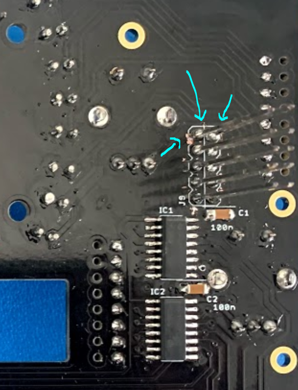
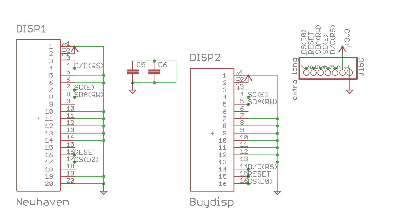
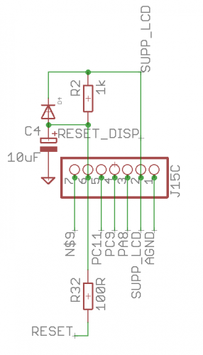
Seems mostly good but I would check the soldering on the waveshare pins again Is the 10uF capacitor correctly oriented? Probably it is but I can't tell from your picture. What is the voltage at the reset pin (should be +3v3)? Below is the J15C pinout. You can check for interconnections at the top of the waveshare pins. I.e. make sure that you get contact all the way through. Net N$9 is the chip select signal that goes to pin 15 of IC2 (also check the soldering there). And here is the same for the display/plate with the connections labelled.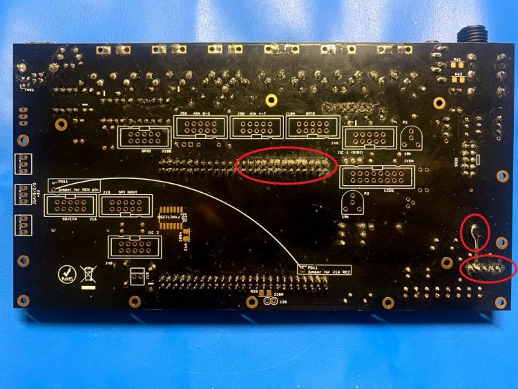

-
LoopA V2 Introduction, Features & Support Thread
latigid on replied to Hawkeye's topic in MIDIbox User Projects
Hi, Maybe the jumper powering the display is not installed? Could you post a photo of both sides of your Core PCB? Best, Andy -
LoopA V2 Introduction, Features & Support Thread
latigid on replied to Hawkeye's topic in MIDIbox User Projects
Your proposed part substitution should work. Check the interboard spacing: 16mm M2 spacer 3M FF header socket 8.26mm TE thru-board header 6.5mm 14.76mm, you have >1mm to spare. FWIW I've used large strips of FF sockets for years, just cut down with a dremel-like tool and you lose that position as the tool "melts through". But it works fine and is cheaper than individual sockets of the right size. -
Right, there are no F buttons on the midiphy SEQ v4+. Here are a couple of approaches: Press 'Exit' until you reach the menu then the 10th button Assign a bookmark to the page; see seq_ui_pages.h for a list of pages to jump to Freely assign any other button that you don't use (e.g. metronome) in the hardware configuration Hack the firmware/code yourself Request such a feature
-
Hi, sure is! Top row is equivalent to Wilba GP buttons. They action items on the OLEDs or e.g. in track mode toggle gates/triggers on and off. Bottom selection row changes function depending on the selection LEDs (around the datawheel/dial). So instead of Wilba's 4x track groups and 4x tracks, you have all 16 tracks available on individual buttons, (up to) 16 step views or whatever the track supports. Likewise you have up to 16 layers available, whereas you only had layer A/B/(C: multipurpose) on Wilba's. Layers are either parameters or triggers, check the amazing user guide here. Other than that it's quite similar, so most of the smaller dedicated buttons will be the same. Shift = Select!
-
LoopA V2 Introduction, Features & Support Thread
latigid on replied to Hawkeye's topic in MIDIbox User Projects
Wow, what a saga! I'm really sorry that you had to go through all of that. I'll discuss with Peter as to how we can compensate you for the trouble. It's the first time we've seen something like this and of course it will be reported to the manufacturer. Seems like fab errors crop up from time to time but it always sucks to get stumped by them. Well done again for sleuthing it out. Hope the rest of the build goes better. Best, Andy -
Getting a bit OT here... Peter and I have been working on this and will have a solution ready for light bleed that could work for existing SEQs too. If you bought the midiphy L4 caps, they don't really like to come off again after insertion. The fully clear ones are safer in this regard. So for L4 caps you might want to wait a bit... Or, there are other light-blocking ideas. Heatshrink doesn't work consistently enough as the bottom will pull away from the switch body. Something like LiquidTape could be a good bet but it is very stinky and you should work outside with it at least or even wear an air filter mask. For keycaps, you could use a nail file (or borrow the better half's) or sandpaper to gently scrape around the stem of the cap, at least at the very tip to bevel the edge somewhat.
-
Would have to try it some time I still don't have my SEQ mounted in its case ; I think the UX idea with illuminating the respective track/layer SB LED seems logical but I haven't played with drum tracks enough. Another one that was intended to be developed was the mute/solo display rather than doubling up on redundancy. An obvious question is how forks in the software are managed if they diverge from the main branch and only Thorsten has "full" commit privileges. But that is a discussion for another thread probably.
-
LoopA V2 Introduction, Features & Support Thread
latigid on replied to Hawkeye's topic in MIDIbox User Projects
Here is the "minimum system" with +5V in red, 0V in blue. Also PA11/PA12 as before. Try pulling off the diode too!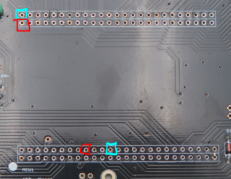
-
LoopA V2 Introduction, Features & Support Thread
latigid on replied to Hawkeye's topic in MIDIbox User Projects
There is no explanation other than a weird TVS diode pulling something up/down. I would try with that removed. You could even only resolder the waveshare with pa11/12 and the +5v pins. Can provide info when I'm back home or you can check the waveshare schem. -
No it wasn't. Peter is into the code now and would know if it can be implemented /reimplemented.
-
LoopA V2 Introduction, Features & Support Thread
latigid on replied to Hawkeye's topic in MIDIbox User Projects
Also that the waveshare is off, could we see that too? E.g. was the crystal desoldered, the jumpers removed, but resoldered correctly for instance? -
LoopA V2 Introduction, Features & Support Thread
latigid on replied to Hawkeye's topic in MIDIbox User Projects
Sure, already suggested: R30 to PA11 (yellow) R31 to PA12 (pink) Other side of the resistors: R30 to USB 3 R31 to USB 4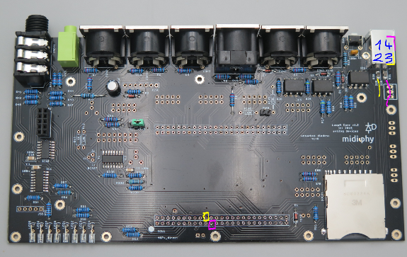
-
LoopA V2 Introduction, Features & Support Thread
latigid on replied to Hawkeye's topic in MIDIbox User Projects
Soldering looks very clean! Was the v407 breakout actually soldered in? If so, impressive that you managed to get it out so well! If it wasn't soldered in, well then the pins probably never had good contact with the LoopA-Core PCB. Other things: try desoldering the TVS diode and powering without it. Also the (soldered -- brave!) optocouplers don't seem to have enough on them, would recommend a touch up. -
I think I notice this behaviour too and it could be improved! What I would expect: From SB Track or layers, press and hold SB Mute, the Sel row controls mutes, also displays on the OLEDs. Releasing SB Mute would revert to the previous Sel. Does that fit with your idea?