

latigid on
-
Posts
2,524 -
Joined
-
Last visited
-
Days Won
149
Content Type
Profiles
Forums
Blogs
Gallery
Posts posted by latigid on
-
-
Okay, actually the r5 boards I've got both share RC (bottom pins on the 2*5 connector) but it makes sense to change the convention.
-
Damn, I had the same issue! The Quad IIC board should come with a warning!
http://midibox.org/forums/topic/14581-4-x-iic-pcb-for-seq/?do=findComment&comment=171360
-
Double post?
-
No, you need different IDs for every PIC in a MIDI chain. But with the bootloader in place there is a change ID app that can be installed using MIOS over MIDI.
-
2 minutes ago, workspace said:
Finally all the soldering is done!
Now I trying to figure out how to get the blm_scalar app onto the PIC.
I read somewhere that I can do this via the SEQV4. But I can't find it anymore (was it on the wiki?)
Or should I upload the app with my RME Fireface?
Nice! You can use two instances of the SEQ MIDI router e.g. USB2 to MIDI in 3 and MIDI out 3 to USB2. Then connect using MIOS to USB2 and you're talking to the miniCore. At least it's how I remember it, maybe if you check back a few pages.
Yep that's right, page 3. This assumes you're using the Quad IIC board and the DIN8 is wired. Another option is to use an old Core8 as it has normal MIDI ports.
-
Idea: track length LIMIT parameter. Accessible on the length page either before or after LOOP.
When programming in longer non-4/4 sequences I quickly get lost within the multiples of 16. What if the active 16 step view was limited to a selectable value (optional of course)? E.g. in "6/8" time with a length of 24, limited to 12 steps. Step view 1 gives 1-12, Step view 2 gives 13-24. To keep within the SEQ hierarchy, this would necessarily reduce the available number of steps of a track.
-
(also French, German, Italian, Austrian and Liechtensteinian)
Saturday 30th of January I will take the SEQ, BLM, sammichFM and MB-6582 to Lausanne's N/O/D/E workshop. So if you want a chance to check out the BLM, meet up with others like Olivier Gillet (Mutable) or get into theremins it's a cool opportunity.
Might see you there!
Andy-
 1
1
-
-
Interesting! I was referring to the SmashTV DIN/DOUT boards and the Core8 module, which I remixed for the BLM. It may be a good time to consider _NG modules for the 32-bit Cores.
-
Good to know, thanks again. But RCs on J8/9 are common, perhaps you're thinking of J19?
Interesting to note that the SEQ PCB doesn't follow this practice. SC and RC are directly connected from header to header.
-
Good to know! I have a PCB with some tight placement, so every mm counts!
-
Okay, the datasheet gives 23.37mm long, is that what you have? So did you stagger the UDNs in the vertical dimension by spacing with extra sockets? Another way might be to put one chip on the top of the PCB, one on the bottom. You have to ensure the inputs and outputs are the correct way around and the power connections will also be mirrored.
Also just to mention; Nico did a few tests with fault testing the UDNs like shorting to ground, bipolar (i.e. negative voltage) CV signals and connecting two UDN outputs together. Everything seems to be okay with the 1k resistors in place. It feels like this could be a more robust solution than using CMOS.
-
I can think of one way to build this into a regular DOUT module; solder the UDN chip in standing up on one row, then wire through hole 1k resistors standing up on the other row. Connect in the middle, avoiding shorts of course. Comme toujours!
But this looks to be a very good solution for level shifting multiple gates/clocks. CMOS chips like the 4504 and 7407 are an order of magnitude faster, but I don't think it's too relevant in our case. Plus these are hex chips with annoying pinouts and unnecessary /OE pins etc. Good job Nico!
-
To me this points out the ADC performance differences between the PIC and STM. Isn't J5 on the latter 3v3 only? You might be overdriving the converter/clipping the diodes etc.
-
I'm working on a sort of hybrid DINX6/DOUTX4 board and I have a question on how to treat SC and RC. The BLM is proof that chaining the clock works even when the DIN/DOUT parts are not equal in length. But on DIN/OUTX4 boards sold by SmashTV normally one splits the J8/9 ribbon with an intermediate header. On this board I have the choice to go serial or parallel, so I wonder what the best way is, or if it really matters.
Many thanks,
-
Before going further, you'll want to check how the reset behaviour impacts the device as Thorsten mentioned above. As all of the reset circuits are linked, applying a signal may interact with other parts with unpredictable results. And looking a bit closer, reset on U20 is an active high signal, so a +5V signal probably has to be applied to your pin 10. Formally this also drives the bases of Q6 and Q7 and activates the two other reset nodes.
One way might be to disconnect that pin 10 out of circuit by cutting the trace (if possible) and using a Core pin to drive reset high or low, but I couldn't tell you how to do that exactly (maybe via a suitable push pull pin + pull down resistor?).
For MIDI in and out, it's not sufficient to wire directly to J11E because MIDI in should run through an optocoupler. It's quite an easy circuit and could be built on a little bit of perfboard. A ready-made solution is at the midibox-shop but I don't know how much room you've got in your box. Having a MIDI out is useful even just as a pass through port for other devices. You could also go old school Core8 which ends up being smaller and has MIDI in and out, but requires a different approach to programming/updating.
It springs to mind that a more compact MCU breakout board could be quite useful for basic "one time control" applications such as this.
-
-
Surprised you didn't throw a WiFi router in there and have, like, totally, no wires, man! I see some room about the TBD for a future expansion. :)
-
1
-
-
Schade!
IC20: pin 1 is not connected, pin 15 is not connected, you are lucky this time! Should still work.

-
3 hours ago, Phatline said:
that was a journey... aufschrauben, das pinout ihrgendwo rausmessen, löten... geht nicht.... anderes core wo gefunden - weils ja nihrgends diagram für core mini für gibt...der ladgid...
Please write in English or at least German! miniCore is just the Core8 minus all unnecessary parts, mostly headers. All pullups are in place and you can easily trace the circuit because it's on one layer only.
Those LED pins are common to RN20 pin 12 then the resistor pin opposite (pin 5) goes to IC20 pin 7.
-
You could use a miniDIN connector, as found on old skool PS/2 mice and keyboards. I think Altitude did exactly that with his BLM (4*16) extension.
-
Are you at the config page and do you assign the BLM port correctly? If a valid MIDI signal is detected it should say "found" within, say, five seconds.
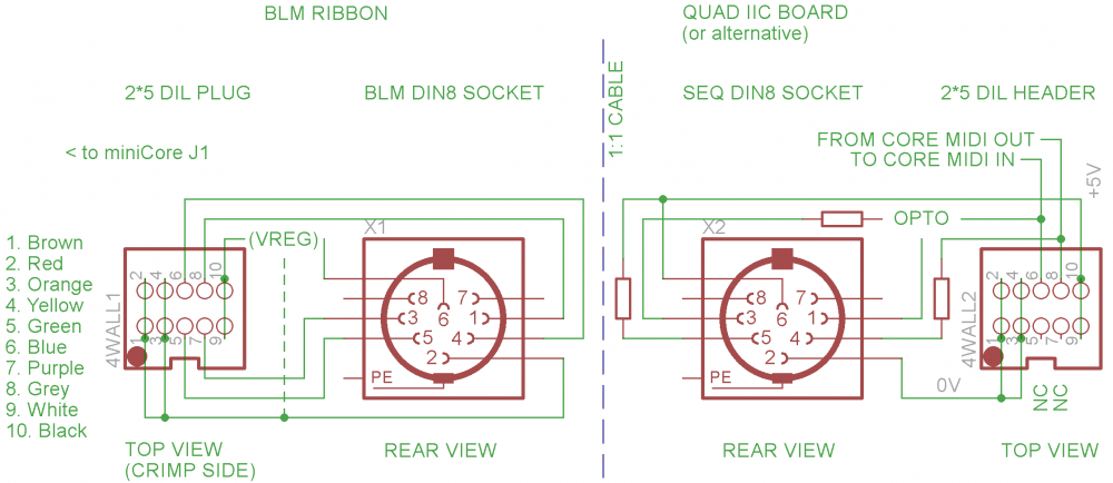
Is the optocoupler installed on the quad I2C board? What connections are you using? A crimped DIL plug? Can you verify these?
-
Nice, is the idea to use the switches bare (no caps)? How are they to play?
Well done!
-
For any past or future travellers, I measured the DIN and DOUT r5 boards (just one example of each):
DIN 100.1*45.2 mm
DOUT 100.25*45.1 mmThickness is about 1.6-1.8 mm.
Both boards have exactly the some mounting hole positions relative to each other, i.e. does not rely on the outer milling.
4.3mm (prepared for M4 screws) centres using the x,y centre of the PCB as the origin with the long axis horizontal:(x,y) =
(-45.525,-18.01)
(-45.525,+18.01)
(+45.525,-18.01)
(+45.525,+18.01) -
Well, on the hardware side you could check resistance from the common cathodes (each group of four are all connected right?) and the mentioned pins on IC18. Left of centre (viewed from the PCB rear) to pin 2, right of centre to pin 4.
I'd still look at RN18 and plug in a miniCore to be sure.

MIDIbox SEQ V4 Release + Feedback
in MIDIbox SEQ
Posted
Yes, I think that would be great for polyrhythmic sequences!