

latigid on
-
Posts
2,524 -
Joined
-
Last visited
-
Days Won
149
Content Type
Profiles
Forums
Blogs
Gallery
Posts posted by latigid on
-
-
12 minutes ago, TK. said:
The Mini-Core module has 4 additional analog inputs which are unconnected, and should be tied to ground to avoid that random CC values are transmitted if the project_with_8_mapped_ains.hex firmware is used.
Alternatively (instead of grounding the pins) you can use the project_with_4_mapped_ains.hex file - because it won't scan the unusued analog pins.
Many thanks for FW updates. I've added them to the OP.
- Check that all diodes and LEDs have the correct orientation
- Those middle 8 LED pairs have their cathodes sunk on the transistors nearby (Q37 and Q35) so check the soldering there, also the adjacent resistors.
- Do all sets of four cathodes show continuity? Are any shorted to ground?
- Bases of the transistors go to RN18 (not labelled on your PCB) pins 12 and 14 respectively
- RN outputs to IC18 pins 4 and 2 respectively
-
 1
1
-
24 minutes ago, Phatline said:
a second pair of Midi-IO, to controll a second device (for example triggermatrix), and a switch or Button-Combination - to switch between the ports, and switch between the 2 Matrix-Arrays to visualize them
(the 2 modes are always up to date, they write the incoming midi notes in the Arrays, also when we are in a other mode, when we go in the other mode, the arrays are dumped out to the leds...)my wish is a stripped down 32bit c-version for the 32bit cores (i know xmas is over...) to study & work with...
Could be wrong, but I think this is already possible by using the MIDI router inside the SEQ. You would still need an app on the other end to work with the BLM MIDI notes. It's a cool idea to re-purpose the matrix though!
-
6 hours ago, Phatline said:
on the upper side where the Silicon Contact-Mats are placed: left to the RN17 - is this RN18?
I ask because the Printing on the PCB is ereased, and i dont find any PCB-Layout File or Shematic (where are they? maybe i need them too if i have troubles.)
thx.
(note: the smd parts was fun and fast to solder, but the wired 1N4148 where Hell, cutting bending, cutting again, bending)
I told you the 4148s would be the most painful part! But they do actually provide a "bridging" function that you don't get with SMT parts.
You've got it right: RN17 is on the top side, bottom right corner. RN18 is to the left of RN17, top side, just before the button pads start.
Schematics available here:
http://www.ucapps.de/mbhp/mbhp_blm_scalar.pdf
http://www.ucapps.de/mbhp/mbhp_blm_map.pdfI don't intend to publish the layout files; seeing as there are very few users I'm happy to help on a case-by-case basis.
-
1
-
-
Strange! I won't be able to help much in the next few days/weeks as I'm moving, but I advise to check around all power connections: capacitors (including tants), pin 16 of ICs and RN1..5, check headers and the R1 bridge. The best way is with a hot air rework station and leaving some sort of continuity check across 5V/0V. Thus when you find the fault you only go as far as needed to rectify it. You possibly have a bridge under a capacitor or the soldermask is scratched and the short joins to the groundplane there. Seeing as you're the second to have this issue, I need to consider more plane isolation in the next run... Hope that you can get it back to a good state!
-
Seems like the icons in reply are messed up? Link gets cog, emoticon gets chain and code gets smiley face. Or is it just me?
-
It might be that you just need to play more :) For me it's clear if the track is not in the current 16 step window because the cursor is not scrolling (assumes the sequence is running). I then glance down to the bottom row and choose the appropriate bar. There are also instances where you might want to fill in notes and then expand the track length.
I find the BLM works like a "macro view" of the SEQ. I.e. there is bi-directional communication when a parameter/screen is updated. (Try to fill up a grid and then adjust the scale for instance!) So display behaviour on the BLM can't be fundamentally different from the SEQ without significant changes to the latter (I think).
Oh, and don't forget 303 mode for easy access to four octaves!
(May I suggest feature requests are discussed in the thread here? Just to keep this one related to build experiences.)
-
Something that isn't documented as far as I can see: Shift+3 and Shift+4 toggle Mute and Solo modes. Could we think about a more optimal way? It seems like the best usage is described on the ucapps page above but not implemented yet?
-
Aha, I was going to suggest checking the optocoupler!
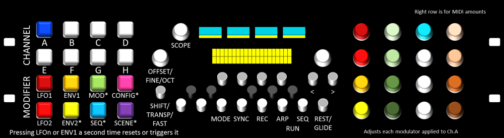
For usage, check out the overview here. An expanded walkthrough could be good at some point.
Have fun!
-
Ha, well maybe the next time I'm in Munich! Sounds like I will have to sit down and try out all of the possibilities as a New Year project.
-
I bet TK. would love to program my idea! :P The SEQ wouldn't send MIDI notes but replace the Note On/Note Off with CC12(13/14/15) 0 and CC12... 128. So every MD track would be full of 16/32/48/64 notes depending on the length and the pattern would form out of muting/unmuting. One could still program parameter locks on the MD! But perhaps it's half-baked because all of the reverb tails and delays would also get gated (I think)...
I wish the pattern entry could be hacked directly! Oh well!
-
Not sure if we're starting new threads for features now, but here goes:
The MachineDrum is one hell of an instrument but to make full use of its best features one can't sequence it externally. But it does respond to CC. So in theory, one could fill up a pattern (every step active on the MD), start the SEQ with the MD slaved, then "sequence" it by sending a CC "unmute" event when the step is active, followed by a CC "mute" event when the step is finished, or just before the next one starts. The MD is set to a "base channel" and CCs are assigned using an offset of +0, +1, +2 or +3.
MD track    Base chan   CC      Value
1           +0          12      0 = unmute
2           +0          13      >0 = mute
3           +0          14
4           +0          15
5           +1          12
6           +1          13
7           +1          14
8           +1          15
9           +2          12
10          +2          13
11          +2          14
12          +2          15
13          +3          12
14          +3          13
15          +3          14
16          +3          15
Caveats:
It would cut a long sample into 1/16th note steps, although you could "tie" a few notes together. In this case only one unmute and mute command should be sent. EDIT no, it would re-trigger on the MD... short sounds only.
Swing, delay and other interesting effects would not work as intended.Any thoughts?
-
Completely off means the other transistors of a row should be checked as well, also all of the pins around those named resistor networks.
You mean the extra column is also off?
Check around the pins for ICs 10 and 14 too.
-
Are the rows completely unlit or only half? If it's the latter then it could be related to the transistors.
Bases (bottom left) of the transistors connect to the resistor networks:
Q29 connects to pin of RN14, Q19 to pin 14 on RN10, Q22 to pin 10 on RN10.
Emitters (bottom right) connect to ground, but other pins shouldn't. Check if there's a short to ground. -
Hmm, this should already be doable with a drum track assigned. You do lose resolution in 16 voice mode though (maximum step length of 64); I wonder if it could be enhanced with the SEQ V4+?
-
This one too:
I think the sVreg is now EOL; I can't say anything about any replacements.
-
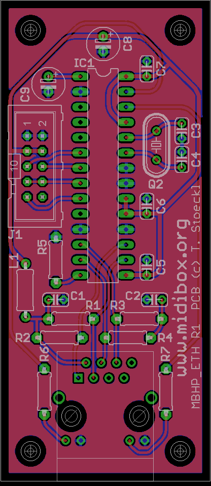
The original layout from seppoman
-
Thanks for your input!
The next step will be to design and build the PCBs. I'm experimenting with colour as a means of easily recognising parameter groups
provisional, some things have changed already -
Thanks, I added the PIC info to the OP.
-
The implementation is unclear and the linked article doesn't exist. What do you hope to achieve? The SEQ already supports 64 (I think) assignable triggers via DOUT pins.
-
Not enough interest to run sorry, perhaps later.
-
Can you describe the pin assignments for pins 1-6 on on the DIN? In other words, which specific pins are used for 0V, 5V, MI+, MI-, MO+ and MO-?
The connections are listed here but at least for me they are very confusing. It's exactly the same on the Quad IIC.
So, I've redrawn the diagram:
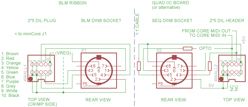
I guess it's complicated because one box's MIDI out is the other's MIDI in. The connections listed have common power on pins 6/2.
SEQ side: MIDI out from the Core is current limited then goes to pin 4. Pin 5 is the pull up to +5V. MIDI in to the Core arrives on pins 1 and 3 and goes to the optocoupler. The optoisolated signal then goes to the appropriate MIDI in on the Core.
On the BLM side, if the connections are crimped by colour/order as I've mentioned, just plug the right way into the miniCore and you're done :). (The order is switched relative to the SEQ side to connect SEQ MIDI OUT <-> BLM MIDI IN and BLM MIDI OUT <-> SEQ MIDI IN.)
Also, I picked up the adafruit verter board. What holes on the verter board did you use to mount it to the main board? I see holes labeled 5, G, PG, PS, G, EN, Vin. My guess is that I shouldn't use the holes labeled 5, G, or Vin.
That's exactly how I mounted it; long side of a single 4 pin header to the muck area (raised up by the plastic on the PCB front side), short side to the VERTER PG, PS, G, EN.
-
Glad to hear it's all glowing now!
For the QuadIIC, be careful with the DIN8 connector that you order as there are two different pin configurations. I ordered twice from Mouser thinking it was my mistake, but their description was wrong. Hopefully they've updated it. They can be had on eBay, if I remember the seller was based in the UK.
-
Hi @ all,
What kind of hollow shaft encoder are you planning to use? And where do you get the clear shafts?
That's for another time when all the pricing, dimensions etc. are known.
-
Pretty sweet!

For the non-illuminated 5, first check the diodes are soldered correctly. Then do the LEDs have the correct polarity? The main grid and extra column are only common from the cathode side. When viewed from the back, the lower contact on the LEDs should show continuity for all of these 5, in fact the first 9 cathodes should all be connected in a row. The second 8 of a row are driven through a separate transistor.
From the topside, is there a slight scratch on the trace just to the inside of the right side of your yellow box? If this trace is somehow cut, please connect cathodes on the 5th and 6th column on the same row.


BLM 16x16+X build guide
in MIDIbox BLM
Posted · Edited by latigid on
@Phatline Gnarly! No warranty for non-standard usage! ;)
@TK. The unmounted pads are for terminating the SC/RC lines. Not required as far as I've seen.