philetaylor
-
Posts
828 -
Joined
-
Last visited
Content Type
Profiles
Forums
Blogs
Gallery
Everything posted by philetaylor
-
No problem, it was fun. I always like learning new things and I have learnt quite a few doing this ! Here is the VST playing a note in Reaper:
-
No need for the current limiting resistor. if the device that it connects to requires 450mA then any 6v supply that 'can' supply at least 450mA is sufficient. You could use a 10A one if you wanted. The reason that you sometimes need a resistor to 'limit current' is when the device being powered has 0 (or very little) resistance of it's own. Ohms law tells us that Current (in amps)=Voltage in volts/Resistance in ohms. So a very low resistance device (like a forward biased LED) could (in theory) draw an almost infinite current. What happens of course is the LED goes pop! If you put a resistor in series with the LED then this increases the circuit resistance and stops you blowing the LED. Every device that you are likely to want to power will have a suitable internal resistance already! Cheers Phil
-
Which part don't you understand??? I assume the bit0/bit1 etc stuff? This just means that for these CCs, the value that you send is made up of various 'bits' Each 7bit MIDI message (0-127) can be displayed as binary as follows: bit: 0 1 2 3 4 5 6 num: 1 2 4 8 16 32 64 So for CC 20, if you wanted Triangle, Pulse and Ringmodulator, you need to add bit0, 2 and 6 together which is 1+4+64=69 so you would send CC20 with a value of 69. Cheers Phil
-
No it was a genuine mistake.... nILS is right though, it is always worth double checking things. As one of my college lecturers always used to tell me "measure twice, cut once!" Phil
-
You are quite correct (it was a deliberate mistake to make sure you are paying attention !!!) Your panel wants to be 217.93x52.58 Cheers Phil
-
Is LC on MBHP_CORE_STM32 module Possible or likely?
philetaylor replied to AdmiralTH's topic in MIDIbox HUIs
The current version of MBLC V2 (CORE32 Version) supports a maximum of 8 motorfaders. This is hard-coded in lc_mf.c. The CORE32 supports up to 16 motor faders. From mios32_mf.h: // number of motorfaders (0-16) #ifndef MIOS32_MF_NUM #define MIOS32_MF_NUM 0 #endif Looking at the code, other than possibly rearranging the LCD display, I think it would be trivial to adapt mblc_v2 to support more motorfaders..... Take a look at: http://svnmios.midibox.org/listing.php?repname=svn.mios32&path=%2Ftrunk%2Fapps%2Fcontrollers%2Fmidibox_lc_v2%2F Cheers Phil -
Hi Freddy. This is what we discussed on the other thread. To be able to do this i'm afraid you are going to have to use assembler. (the sample code from the dog_g driver that I sent in the other message is a good start!) The problem is that MIOS_DOUT_PinSet takes quite a few instructions: andlw 0x7f lfsr FSR1, MIOS_SR_DOUT_0 rgoto MIOS_SRIO_Set1 MIOS_SRIO_Set1 movwf MIOS_PARAMETER1 rlf WREG, F swapf WREG, W andlw 0x0f addwf FSR1L, F movf MIOS_PARAMETER1, W andlw 0x07 call MIOS_HLP_GetBitORMask iorwf INDF1, F return I haven't counted but this is at least 10 clock cycles on its own! If you take a look at the dog_g driver in more detail you should see how SPI in software can be achieved.... You can also look at the sdcard driver for 2 way communication. Thanks phil
-
MB-SEQ V3/V4 Control Surface PCB and matching case
philetaylor replied to Wilba's topic in MIDIbox SEQ
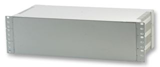
As I would like to put my MB SEQ in a case, I have been looking around for rack enclosures and I found this: It is available from Farnell: http://uk.farnell.co...jsp?sku=1526725 I have ordered the 3u black one. my thought is as the front panel is removable I can just fix my panel on top of the rack ears. Also being ABS, I can cut holes/slots in the back without too much trouble. I will post some pics when it arrives. Cheers Phil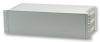
-
It's on the same .pdf that's available on the above link (215.24mm x 49.78mm) Phil
-
No sorry it isn't that straight-forward. The MIOS8 C API and the MIOS32 one are completely different.... I don't know how far forward TK is with the MIOS32 version of the MIDIbox MM (or if he has even started it). It may be possible to modify the MIOS32 version of the LC if you have a reasonable knowledge of C programming! Thanks Phil
-
Good to hear, I suspected that it was LCD related as the glcd_font module is only included by the glcd modules. Cheers Phil
-
Latest SVN works fine for me! What LCD environment variable (MIOS32_LCD) have you got set? Thanks Phil
-
MB-6582 head bolts, nuts, screws, washers etc etc
philetaylor replied to highrider's topic in Parts Questions
Hi Vlan. That part looks like a spacer to me (not a bolt/screw!) I can't find any 25mm countersunk bolts/screws on the Conrad site. From Farnell, I have found this: http://uk.farnell.com/tr-fasteners/m325-ksstmcz100/screw-slt-csk-steel-bzp-m3x25/dp/1419379 which is what you are looking for. Thanks Phil -
MB-6582 head bolts, nuts, screws, washers etc etc
philetaylor replied to highrider's topic in Parts Questions
Hi. I tend to use Farnell http://uk.farnell.com/ for lots of this stuff. M3x10mm threaded spacers are about 10p each: http://uk.farnell.com/ettinger/05-03-103/spacer-m3x10-ni/dp/1466761 I had the same experience with this sort of hardware on Ebay.... Cheers Phil -
Hi. To support SPI in MIOS32 (EDIT:I meant MIOS8. MIOS32 has multiple SPI ports!), you need to "bit-bang" the data (i.e. manually send it as a stream of data) The SPI based LCD drivers (dog_g) demonstrate how to do this: USER_LCD_ShiftByte USER_LCD_ShiftByte_HLP MACRO bit bsf USER_LCD_LAT_SCLK, USER_LCD_PIN_SCLK ; rising clock edge ;btfss WREG, bit bcf USER_LCD_LAT_SDA, USER_LCD_PIN_SDA ; set SDA depending on current MSB btfsc WREG, bit bsf USER_LCD_LAT_SDA, USER_LCD_PIN_SDA bcf USER_LCD_LAT_SCLK, USER_LCD_PIN_SCLK ; falling clock edge ENDM USER_LCD_ShiftByte_HLP 7 USER_LCD_ShiftByte_HLP 6 USER_LCD_ShiftByte_HLP 5 USER_LCD_ShiftByte_HLP 4 USER_LCD_ShiftByte_HLP 3 USER_LCD_ShiftByte_HLP 2 USER_LCD_ShiftByte_HLP 1 USER_LCD_ShiftByte_HLP 0 nop bsf USER_LCD_LAT_SCLK, USER_LCD_PIN_SCLK ; rising clock edge return As you should be able to see from this it "bangs" each bit seperately! This is quite resource intensive but is ok for fairly low volumes of data. You are quite right, for SPI you need a CS/SS line for each device so you would need a total of 12 output and 1 input lines (10 x CS, 1 x Data in, 1 x Data out, 1 x Clock). IIC (I2C) is probably a better bet as you are not going to be using a large amount of data and the PIC has a dedicated IIC port. The limit of 8 devices is a limit imposed by the MBHP_IIC module and not the IIC bus itself (it uses 3 bit address selection jumpers) so as long as the device that you are using allows it, you could (in theory) connect over 100 digital pots to a single IIC bus! With the Core type, I would probably go for the STM32 as it is much easier to program and is much more powerful. The downside is that not all of the midibox apps are available yet and what is available aren't as "mature" as the CORE8 versions. Cheers Phil
-
Did anyone manage to order? I was trying to get a beagleboard as it looks fun: http://www.sparkfun.com/commerce/product_info.php?products_id=9444 but I could never get far enough to actually order.... SparkFun Free Day Has concluded! $100,000.00 was given away in: 1h : 44m : 50s Phil
-
As I obviously can't help you either, I will follow Thorsten to the door
-
Although it is against my better judgement as I like nILS live in hope that this is indeed a language barrier problem I am going to respond to this (funny how sarcasm seems to work in any language though.....) A Core32 PCB with pre-soldered STM32 chip is $25.95. Add about $3 for the crystal, capacitors and resistors and you have something that is functionally equivalent to the Stamp that you mentioned. You would need to be a VERY slow solderer to take hours to solder this handful of through hole components. I calculate a complete Core32 parts kit (with all other components, PCB and STM32) to only cost $45.95 from SmashTV Phil
-
MIDIbox SEQ - Things start to clear - some questions [solved for now]
philetaylor replied to gjvti's topic in MIDIbox SEQ
Hi. EDIT: You beat me again TK, this is getting to be a habit :tongue: The Wilba bulk order hasn't exactly stalled, in fact a mini bulk order was completed last month (12 units). You are correct though that the main bulk order hasn't been active for quite a long time. I really am not sure what the best thing to recommend with this? If a full bulk order is in the works then I would definately recommend going for that as it is a really neat solution (I am on the small bulk order and hope to receive my kit later this month!) If you definately wan't a V4 seq then no need to buy the whole V3 kit (as that also includes a CORE8 kit that you won't use). Also as the CORE32 comes with 2 MIDI ports (+ USB MIDI) you may not need the IIC modules either as each IIC module just adds another MIDI IN/OUT. Personally, if you are already ordering from SmashTV (avishowtech) then I would get the DIN and DOUT modules from there as well. His PCB's are fully silk-screened whereas I don't believe that Mike's are... Therefore (assuming you can't get a Wilba PCB), you will need: 1 x MBHP_CORE32 3 x MBHP_DINX4 1 x MBHP_DOUTX4 2 x (2x40) LCD modules Buttons - any single pole button is fine (depends on your front panel) LED's - again whatever ones you prefer (except blue/white as they will kill your retinas :)). Decoders - if you search the wiki/forum you should find models of supported decoders. Banksticks are not supported on the v4 SEQ so you will need an SDCard reader. There are a few options in the SD Card section of the ucapps.de website http://www.ucapps.de/mbhp_sdcard.html As I said before, there are various places that this information is available but unfortunately it isn't always that easy to find. As I start, I would recommend clicking on EVERY link on the left hand side of ucapps.de and READING EVERYTHING :). Although you are only interested in the SEQ V4, the other projects all use the same basic hardware and there are numerous hints and tips. The one thing that you don't need to worry about is the Software though, TK has that sorted! Phil -
MIDIbox SEQ - Things start to clear - some questions [solved for now]
philetaylor replied to gjvti's topic in MIDIbox SEQ
the MBHP (MIDIbox Hardware Platform) is a range of modules that can be used to create numerous MIDI capable hardware devices. One of these is the MIDIboxSeq. Mike offers a bundle of all of the MBHP kits that you will need to build a MIDIboxSeq V3 BUT this doesn't include any switches/encoders/LED's/LCD's or a case/front panel. These would need to be purchased seperately. You can also buy the individual kits from SmashTV (in the USA). There is also Wilba's MB-Seq which is a very neat front panel design and PCB http://www.midibox.org/dokuwiki/doku.php?id=wilba_mb_seq'>http://www.midibox.org/dokuwiki/doku.php?id=wilba_mb_seq there will be a fully cased kit that will be available at some time in the future. The beauty of this design is the PCB has all of the necessary DIN/DOUT modules so only requires a single connection to the CORE module. The difference between V3 and V4 is which MBHP_CORE is being used (the brains of a MIDIbox). All versions up to and including V3 used the PIC based CORE8 whereas V4 is based on the new STM32 based CORE32 (much quicker, much more memory). As all other MBHP modules are compatible, the upgrade from V3 to V4 is simply to swap the boards over (and re-wire the LCD connection as this has changed). There is lots and lots of information about all of the MIDIbox projects at http://www.ucapps.de http://www.midibox.org/dokuwiki/ and on this forum but some of it does take a bit of digging to find! Thanks Phil -
Oh TK, you beat me to it... I was going to say: ... a replacement for what ??? It costs much the same as a CORE32 but doesn't include any of the voltage regulation, LCD interfacing electronics or MIDI ports and wouldn't easily interface with any of the existing MBHP modules...... Phil
-
MB-SEQ V3/V4 Control Surface PCB and matching case
philetaylor replied to Wilba's topic in MIDIbox SEQ
Yes with my LCD I have used 8mm standoffs (sitting 2mm in the blinds) and the LCD just sits away from the front (enough for me to put some 2mm perspex in the slot. Phil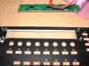
-
Hi. The tagline for the MIDIbox project is "Non-commercial DIY Projects for MIDI Hardware Geeks". The key word is really DIY (Do It Yourself). Many people here will happily help you to realise your controller but you will struggle to find somebody here who will build it for you. If you don't want to 'butcher' the controller then you will need at least a circuit diagram for it to work out if what you want to do is even possible, but looking at the picture, if everything goes down that single ribbon cable then it must be multiplexed in some way which I doubt is going to be easy (or even possible) to work with. Thanks Phil
-
You're welcome, glad it's all working for you. I would love to see some pictures of the finished project! Just to clarify, the tutorial isn't exactly wrong, it is just based on a different LCD to the one you have :) Phil
-
If the BC337 was dead then you wouldn't see 5v between the A and K of the backlight (which I think you said you have). Are you SURE that you have it the right way round? pin 15 on the LCD is cathode (-) and pin 16 is anode (+) so they should go to B- and B+ on the CORE. Another possibility is that the backlight has solder bridges that may not be linked, can you check continuity between pins 15/16 on the LCD and the actual connections to the backlight? Looking at the datasheet, it is possible to switch the polarity with different bridges. Assuming you have the DEM 40271 SYH-LY, this might be your problem, take a look at: http://www.soselectronic.hu/a_info/resource/d/dem/dem40271sy-ly.pdf Phil