findbuddha
-
Posts
267 -
Joined
-
Last visited
Content Type
Profiles
Forums
Blogs
Gallery
Everything posted by findbuddha
-
Simple Transport controller for Ableton/logic/protools?
findbuddha replied to Googleberry's topic in MIDIbox HUIs
Fair go, it can be a difficult decision to make when you have to choose between: a - reading the forum for hours to find the info or even just the search term b - posting what may be a stupid question in the hope that someone more knowledgeable can take 1 minute to tell you the answer. :unsure: -
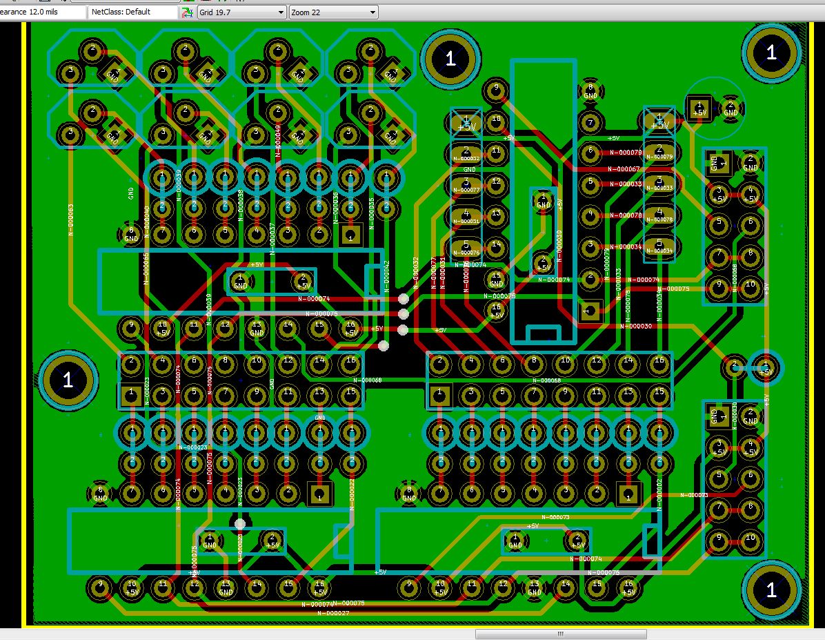
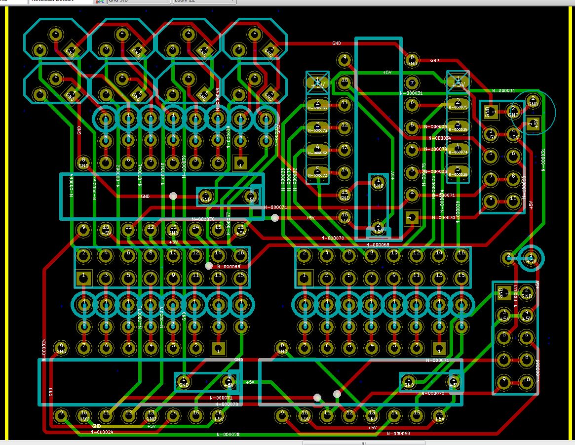
I appreciate your help :) I think I'm getting closer: - 12mil spacing - 16mil traces except for a couple of 14mil that go between some pads. - ground plane seems a little better utilised.
-
Ponoko front panel for Wilba's control surface pcb
findbuddha replied to findbuddha's topic in MIDIbox BLM
My PCBs will be using 6mm switches, probably either E-Switch TL1105BF100Q or Panasonic Light Touch Switch EVQ-PAC09K. For my planned DIY illuminated setup, the switch actuators will need to be the correct height. I'll be getting a small PCB and ponoko panel/buttons done up to test the concept. Here's my current ponderings (stuff on the right hand side is for a mixer/LC): Any suggestions? :)

-
Where does one find such cute little brackets? /stupid question
-
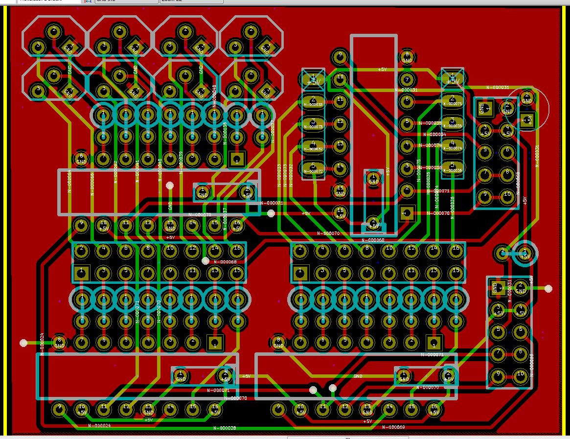
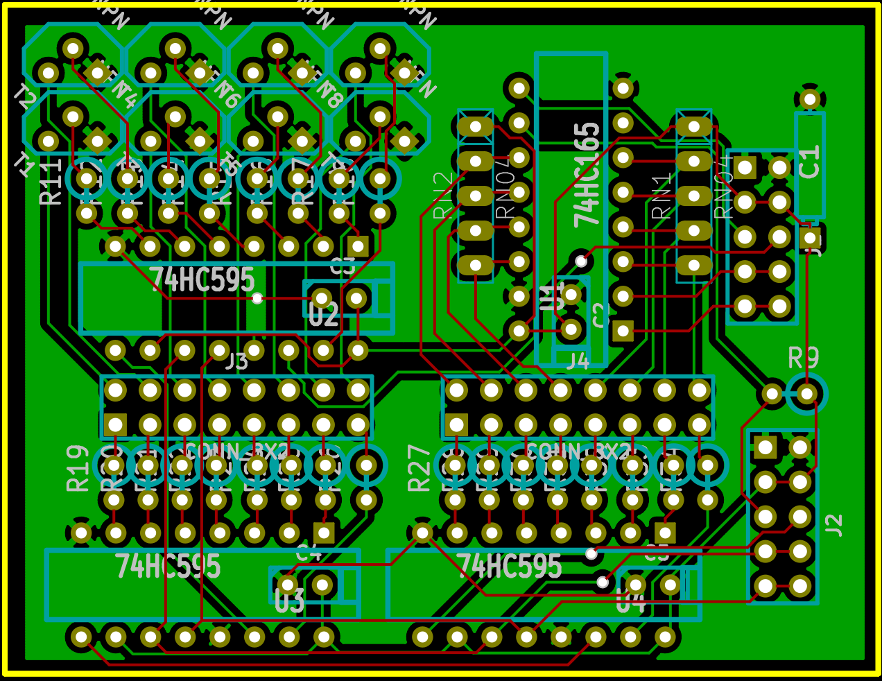
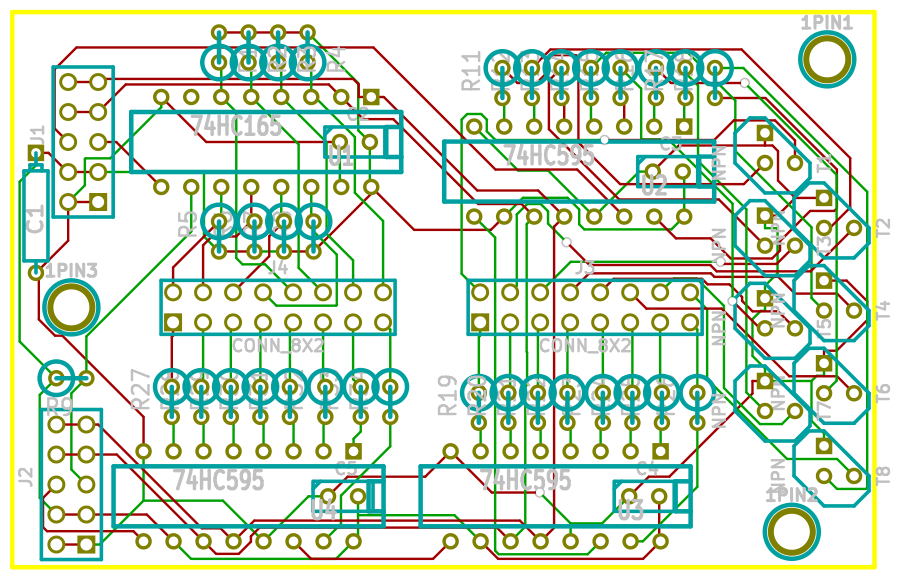
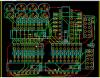
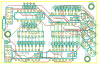
Here it is, redone with 16mil traces, 10mil clearance. Passes kicad DRC. These are direct screenshots from kicad, instead of the poorly layered render I did last time. I've attached one with GND plane, one without. Am I getting closer? (Still a few components need moving a little, mostly caps) Thanks :)
-
It passed Kicad's DRC..... Tracks too thin? Ok, I will try 16 mil traces.... Too close to pins? Do you mean for manufacturing, or electrical interference? I have used 10mil minimum clearance: the two manufacturers I might use specify 8mil (PCBCart ) and 7mil (Gold Phoenix). Delete that layout? :shocked: Can you please suggest a better layout? I've already spent many hours deleting and starting over :sorcerer: I just looked at TK's protoboard layout http://midibox.org/forums/index.php?app=gallery&module=images§ion=viewimage&img=277 Seems to have IC1 a long way from IC2 - I didn't realise such long SC/RC lines would be acceptable??? Thanks for your help :)
-
Tits on a bull????? :frantics: OK, thanks for all the auto-router info. I've gone and layed out the components more intelligently :thumbsup: , and routed it manually (still using Freerouting.net). Any more tips? Ta :)
-
oh.... Could you briefly tell me why? freerouting.net seems (to my eye) to do a nice job of connecting everything, then optimizing it. What should I be doing to route this design that an autorouter can't? Thanks! *edit* I re-did it with GND and +5V planes, and it looks a bit neater.....
-
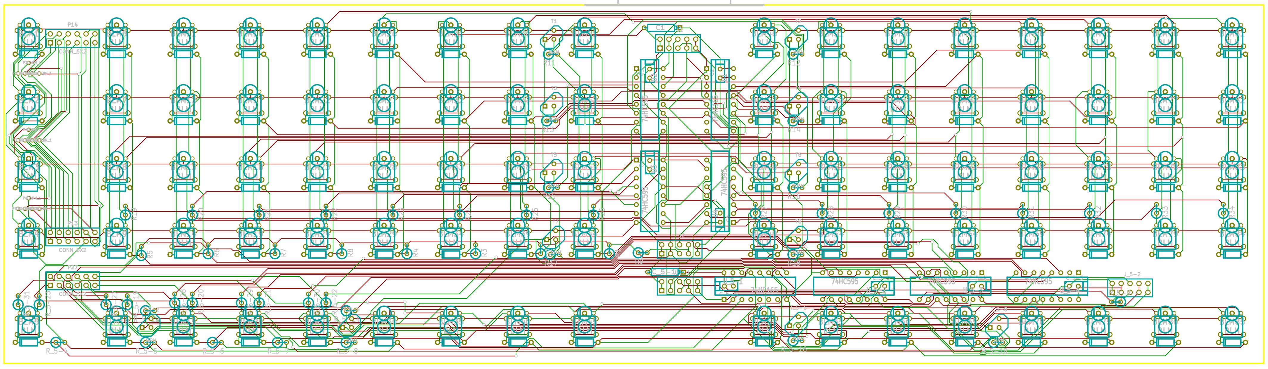
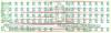
More noob PCB meanderings: I've gone back to separate Scalar PCB..... I manually routed the 'long' connection between J1 -> shift registors -> J2, then let the autorouter do the rest. Any suggestions? :)
-
Ponoko front panel for Wilba's control surface pcb
findbuddha replied to findbuddha's topic in MIDIbox BLM
I did alter the dimensions of the LCD cut-out and the matching clear panel, in line with Wilba's suggestion. I'd be cautious rack mounting using the acrylic - I don't know how strong it is? I'd also suggest anyone using/modifying the files I've posted in this thread to check things over, as I've sold my Seq CS PCB (to make my own, more suited to me), and won't be using this design as posted. :) -
Core32 <-MIDI-> Core8 <-J8/J9-> BLM
-
Well, here's a first pass at it. Need to give more space for the extra row so it can be broken off, and add all the mounting holes.
-
Here's my libraries. The PEC11 stuff is converted from the eagle library found in the midibox wiki. I haven't built a board with them, so I can't verify that they're good. :) Library.zip
-
Also, is it safe to leave unconnected the unused pins on the shift registers for the extra row/column BLM_Scalar?
-
My initial attempts at integrating a Scalar module with a BLM layout seem to suggest it’s possible, but I know little about the electronics involved so I must ask: Is it ok to distribute the transistors around the board…. Ie. have them far away from the shift registors? What about the resistors? I know I must maintain the path of the signal chain between J1/J2 as mentioned in TK’s BLM_Scalar schematic. Ta :)
-
That's what I meant, didn't explain myself clearly enough. I've been looking at PCB Cart: 14"x4", 2 designs per panel (4x16, extra row), to match Seq panel layout Tooling: $ 80.80 Unit cost: $ 17.68 (4) $ 8.44 (20) 14"x4", 5 designs per panel (4x16 and extra row, both split with 'spacer' board in middle), to allow matching Seq panel layout or square layout Tooling: $ 110.18 Unit cost: $ 17.68 (4) $ 8.44 (20)
-
Wilba, or other PCB masters: Looking at your layout here, I see that you've got 2 separate boards (4x16, 1x16), with pads right at the edges to connect the relevant traces. Is it feasible to get this manufactured in a single job? Is V-score or Tab routing best for this situation? It seems to me a way to avoid set up fees of 2 separate jobs. (I'm a PCB newb)
-
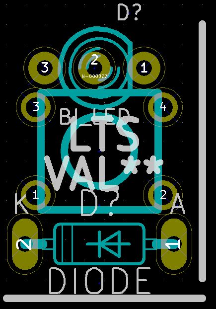
Echo, Wilba’s PCB is designed exclusively for the button pads available from Livid. I will design a PCB as you suggest, with 3mm LEDs, 6mm tacts (probably Panasonic LTS). LED will be ‘sitting’ on the switch base, as close as possible to the actuator. The actuator will be just tall enough to use a flat DIY button cap for illuminated button goodness, or it should be possible to drill your own separate LED and switch holes. I’ve attached my draft arrangement of switch/LED/diode. I’m waiting for TK’s ok on my alternate schematic. The BLM16x16 requires its own Core8, and 5x BLM_Scalar modules (analogous to DIN/DOUT). The BLM is connected to SEQ via midi.

-
My plan with the tactile switches would be to do similar to TK's DIY approach, but with laser cut acrylic caps on top of the silicon sheet. They could be engraved/infilled, and even swapped around if I decide to change button functions. The specific switches I'm looking at could also be used 'non-illuminated', with the actuators and LEDs sticking through simple drilled holes in a panel.
-
Here's the full size image of the schematic. mbhp_blm.zip
-
Kingbright have a 3mm LED with narrower spacing available at Digikey: WP3VEGW It's still diffused though. Is this the sort of thing you mean from ebay? http://cgi.ebay.com.au/500-3mm-Dual-Bi-Color-Red-Green-Bright-3-Pin-Led-RG3L-/300365559276 As far as I can see it's common cathode, bright and with clear lens. I'm becoming less convinced about the benefits of the livid pads, at least for my own use. - Inflexibility of the layout - Limits use to buttons from one vendor, as Wilba mentioned - Cost - I'm going to need at least 300-350 buttons for my control surface + BLM --- Livid pads 5x (8x8): $150USD --- E-Switch TL1105BF100Q 300x: $30USD --- Panasonic Light Touch Switch EVQ-PAC09K 300x: $56.70USD So, people who have the livid pads: do they feel GOOD? :)
-
GIMP managed to convert it - here's the schematic in one image file. Also includes some 'do not connect flags' that I had omitted. *Attach files isn't working now*
-
Schematic done, except for labelling each component, and adding connector between the right and left sections of the extra row. I’ll leave those things until I get the green light. I’ve attached the Kicad schematic file, a SVG export and screenshots – Inkscape crashes when I try to export to a more friendly format. mbhp_blm_schematic.zip
-
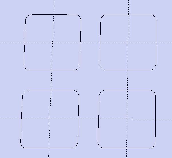
OK, that certainly looks different to the one I’ve got. I just tried it in Eagle Light instead of Kicad and I see what you got. There must be something going wrong with my conversion from Eagle library to Kicad for the round ones. I’ve sent Livid an email asking whether they’ll fit.
-
It’s not the contact on the PCB I’m concerned about, it’s the hole in the button. The ‘inner circle’ (which I assume corresponds to the size of the hole in the button) is the same in both the rectangular footprint and the circular footprint (both of which are in the livid.lbr.zip). :)