findbuddha
-
Posts
267 -
Joined
-
Last visited
Content Type
Profiles
Forums
Blogs
Gallery
Everything posted by findbuddha
-
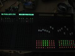
Problem solved with my SEQ control surface - I had resistors on the cathode DOUT lines. Thankfully my PCB design was OK, just had to mod a DOUTX4 board.
-
Problem solved. I had resistors on the cathode DOUT lines. *kicks self for not reading wilba's schematic properly*
-
I doubt you've damaged anything but I wouldn't know for sure. The 4x16 BLM is actually a part of the SEQv4 app, and the shift registers should be connected to the same core module as your sequencer. This won't work for the 8x16 setup you want though. It should be possible to code your own BLM driver, have a look at http://svnmios.midibox.org/ for existing apps and examples if you haven't already. I think the difficult thing will be interfacing the 8x16 BLM with the SEQv4 app. If I recall correctly TK said he wouldn't support sizes other than 16x16.
-
Unfortunately that's the wrong schematic for the BLM_Scalar app.
-
I'd sure appreciate the help too Between uni and personal issues I haven't touched the midibox in a couple of months. When I get to around to troubleshooting the first thing I think I'll try is testing some different DIN/DOUT boards.
-
Alternative USB MIDI Driver for WINDOWS 7 64bit
findbuddha replied to Gridracer's topic in Tips & Tricks
I don't recall the error code, but I've had the device is not working error happen many times with older versions of Seqv4. Haven't tried the latest yet. Win 7 64bit. -
heinzihogo, I have made a working PCB for the PEC11+SW with KiCAD. I can't remember exactly if I ended up changing the Ilmenator's footprint (I think I did). I've attached my library files for you to try. As always, I recommend you checking for yourself before spending money on PCB :) fb-kicad-library-21-09-2011.zip
-
Thanks latigid on :) This is probably a better link now: http://www.midibox.org/dokuwiki/doku.php?id=findbuddha It's got most of the design files for my midibox, and more importantly, lists the current known issues. Unfortunately my midiboxing time has been severely restricted over the last 2 months and I've been unable to troubleshoot the problem with my seq matrix. Hopefully I'll get back to it soon.
-
I just bumped into this over on the DIYaudio forums. I haven't tried it but they seem very cheap: http://www.audesine.com/proto-pcbs
-
I'm not in the market for a mixer, neither do I use one apart from occasionally my RME soundcard, but.... My gut feeling is that the project would be more worthwhile if it weren't using volume control chips. I'd try it a: as discrete analog mixer or my personal inclination: b: using DSP like SigmaDSP family which is easily programmable via GUI software http://www.analog.co...sors/index.html
-
MBHP_ETH, MBHP_SDCARD, SSM2044, SSM2164 PCB Bulk Order
findbuddha replied to seppoman's topic in Bulk Orders
I've seen people mention suitable SDCARD adaptors here and there - it might be good for there to be an officially recommended one - or maybe SmashTV could sell one? -
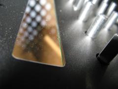
My Ponoko windows are 3mm thick, 1 piece. They are not glued, simply dimensioned correctly to be held in with friction. I believe this is how the sammich* kits work (I used tips from Wilba to do this). 2mm thick clear is also available from Ponoko New Zealand. I haven't checked the other hubs. I'm not sure how well it would work with thinner front panels (mine is 3mm acrylic). Also, my LCD will be flush with the rear of the panel/window - Optrex LCD + 9mm spacer.
-
I paid $6.92USD (+ shipping) for 4x windows to suit 2x40 LCDs. They fit almost perfectly with a tiny bit of sanding to the window at the corners, though I'm sure I could have altered the design to suit. Done at ponoko using 3mm clear acrylic, but they also have various tints and thicknesses down to 2mm in clear. Pic added to my gallery here: I can do a brief guide on getting them to fit if anyone would like to try.
-
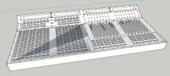
findbuddha's midibox adventures
Images added to a gallery album owned by findbuddha in Members Gallery
-
-
From the album: findbuddha's midibox adventures
-
I'm trying to maintain a complete list of issues on the wiki page... My small BLM that is fully soldered is the 5x17. It's just the lowest 5 rows cropped from my (original) full 16x16+X. In general I'll be posting design files exactly as I've used them - the 5x17.brd contains the error documented here: The blm-full.* design files are for the full 16x16+X. They have been corrected for the above error, but have not been tested. I should be able to order it in the next month or two. Hope that makes sense :)
-
There's this: http://www.seeedstudio.com/depot/dso-quad-4-channel-digital-storage-oscilloscope-p-736.html?cPath=174 ?
-
I've got a wiki page up now, with some of my BLM design files for your perusal. There's a list of current issues which is required reading before downloading. I'm going to attempt a slight relayout of the BLM to allow for more sensible mounting hole locations, but I'm not sure I'll achieve it. http://www.midibox.o...p?id=findbuddha :)
-
Great idea! Thanks for sharing. I have been a little concerned about dust getting into my motor faders.
-
How did Wilba do it? SEQ V4 CS with only 6x74HC165 & 2x74HC595
findbuddha replied to Hawkeye's topic in MIDIbox SEQ
Have a read here: http://ucapps.de/mid..._manual_hw.html And in the hwcfg folder of the Seq application download. The matrix isn't needed for a control surface for the sequencer, it just makes it more compact / use less shift registers. The matrix should be achieveable with regular DIN/DOUT modules. -
KiCAD has one too.
-
As far as I know the software is mostly coded: http://svnmios.midibox.org/listing.php?repname=svn.mios32&path=%2Ftrunk%2Fapps%2Fcontrollers%2Fmidibox_lc_v2%2F But you'll essentially need a PIC core anyway if you want touch sensitive faders:
-
No worries - thanks for all your hard work :)
-
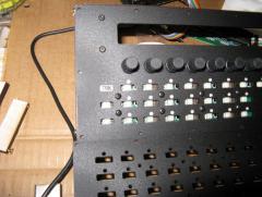
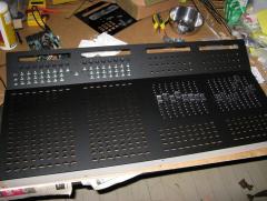
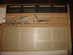
TK, As far as I can tell from the schematic it's not the cathodes that are swapped but the LED anodes. (I think that is the correct terminology) Comparing extra row buttons 1-4 and 5-8 with 9-12 and 13-16, for eg. Switch 1, 5, 9, 13 -> I0 Red 1, 5 -> R0 Green 1, 5 -> G0 BUT: Red 9, 13 -> R3 Green 9, 13 -> G3 I've attached an image of my PCB which I think is consistent with the schematic. I'll have the full design files up on my wiki page once I've got this sorted. Also, I realised that for this PCB I'll need to mod the following section, as I don't have the full chain of BLM_SCALAR preceding the +X section. I'll have to have a think about it. // BLM16x16 LEDs led_mod_ix = chn >> 2; led_row_ix = ((chn&3) << 1) + ((note >> 3) & 1); led_column_ix = note & 0x7; modify_led = 1; Thanks heaps :) :flowers:

-
TK, can you please check the schematic in mbhp_blm_map.pdf? In the extra row, buttons 9-16 have the LEDs mirrored in their groups of 4 with respect to the switches. To explain another way, on my PCB, if I push button 9, LED 12 will light, and vice versa. Also, could you please offer some guidance as to how I should modify the scalar app(MIOS32) to remap these? This PCB is 5x17 version of the full BLM16x16, just to use for buttons for a mixer section ie. mute, solo, arm etc. So I won't need the 'packed format' pattern matching, just toggling of specific LEDs on MIDI in and button push. I suspect I need to do my remapping in this function: if( note <= 0x0f ) { // BLM16x16 LEDs led_mod_ix = chn >> 2; led_row_ix = ((chn&3) << 1) + ((note >> 3) & 1); led_column_ix = note & 0x7; modify_led = 1; } else if( note == 0x40 ) { // extra column LEDs led_mod_ix = 4; led_row_ix = (chn&3) << 1; led_column_ix = chn >> 2; modify_led = 1; } else if( chn == 0 && note >= 0x60 && note <= 0x6f ) { // extra row LEDs led_mod_ix = 4; led_row_ix = 1 + ((note >> 1) & 6); led_column_ix = note & 3; modify_led = 1; } else if( chn == 0xf && note >= 0x60 && note <= 0x6f ) { // additional extra LEDs led_mod_ix = 4; led_row_ix = 1 + ((note >> 1) & 6); led_column_ix = 4 + (note & 3); modify_led = 1; } and also maybe in DIN_BLM_NotifyToggle depending on what MIDI feedback I can get Reaper to give me. Thanks :)