findbuddha
-
Posts
267 -
Joined
-
Last visited
Content Type
Profiles
Forums
Blogs
Gallery
Everything posted by findbuddha
-
From the BLM forum ages ago: So I bought 500 of the clear, 'bright' LEDs from ebay, and compared to the LTL1BEKVJNN Wilba used in MB-SEQ they're - not as bright - don't diffuse as nicely through my illuminated acrylic prototype caps The ebay ones also don't have a polarity marking, and took at least 7 weeks to arrive. At least I got them cheap.Yes, I've learned to hang the postage cost and get samples before buying in bulk. :thumbsup: Does anyone have a better suggestion than getting the LTL1BEKVJN? I'd prefer to shop at Mouser, but if there's a smashing deal somewhere else I'm interested. I've searched Mouser and the only options that are brighter are significantly more expensive. Cheers :)
-
No problem, just wanting to check I wasn't barking up the wrong tree. I'll post my updated libraries after I get my boards back.
-
Did you ever use these? I was just checking over the footprint for the PEC11-Switched and it doesn't seem to match the data sheet very well.
-
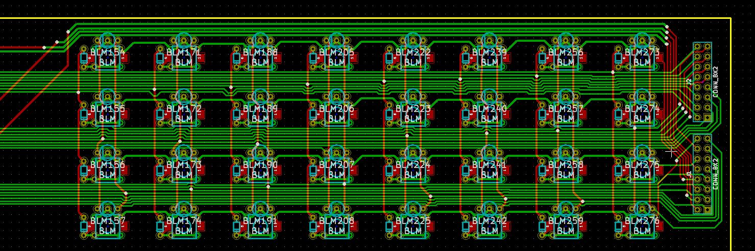
Cheers. As space is tight, I've added a single solder pad near each set of headers. A cut resistor leg between boards should be plenty to hold them together, and not be too difficult to remove if needed.
-
:thumbsup: Thanks for picking that up. I should have created the proper footprints for them. I'll have to use the 'bare' board stacking style headers that take up less space. Any idea how easily they wiggle loose? We're talking 2x 2x8 headers holding up each ~5cmx5cm board.
-
Moving right along.....:sorcerer:
-
Is it possible to simulate the LED duty cycle of BLM_Scalar with a Core32 + DOUT module? I want to check the brightness of the LEDs I've got before ordering more. Thanks :)
-
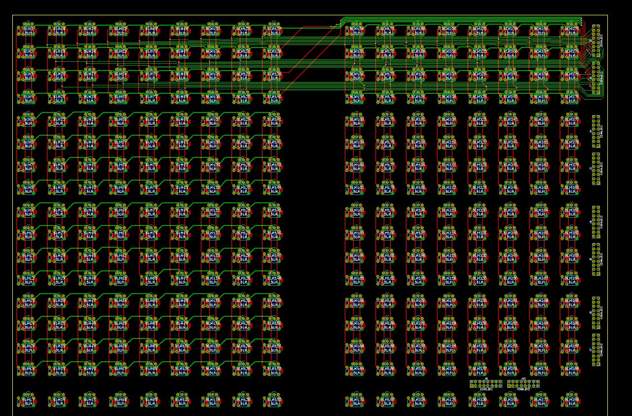
Well, scratch that last post. I've gone back to a slightly more compact version of my original layout, as it's easier to layout the button board. This layout should be usable for both 'horizontally compact' and 'SEQ CS aligned' options, with a simple drag of components. There's a footprint for standard 6mm tactile, as well as ALPS SKPG switches (quiet action, tactile feel: http://www.alps.com/.../SKPG_list.html). Comments please? :frantics: (I know I haven't added mounting holes to the button board yet - there's space between the buttons)

-
Anyone try using PCB Artist (from 4pcb.com)?
findbuddha replied to m00dawg's topic in Design Concepts
There's also KiCad -
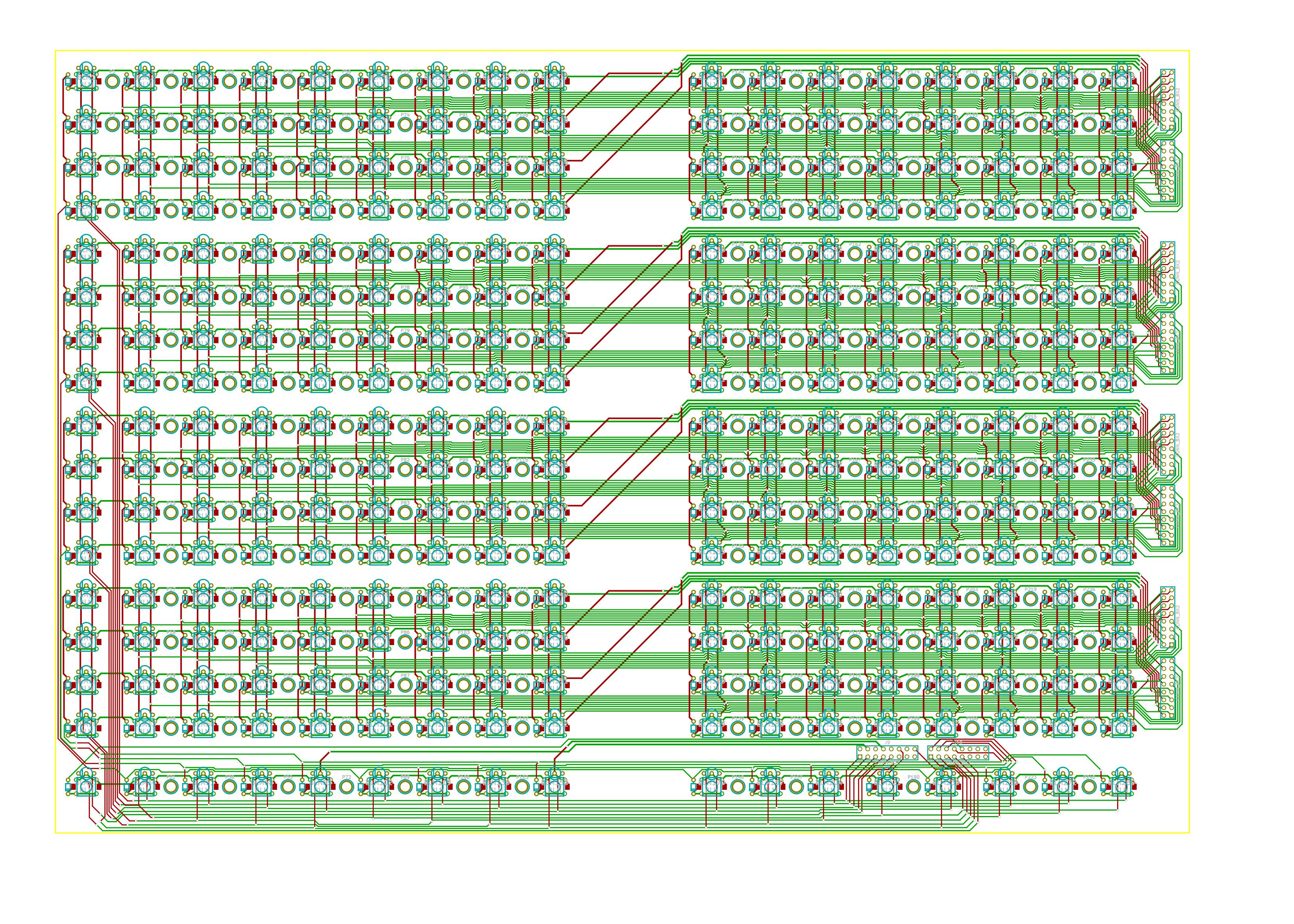
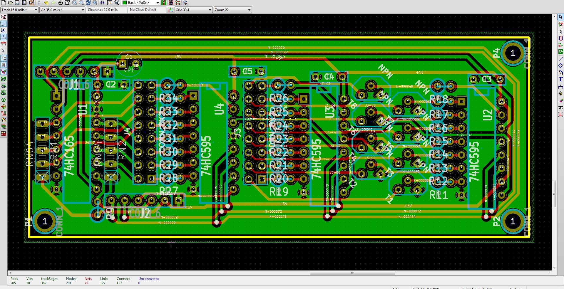
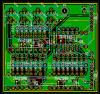
Complete redo, for various reasons..... Based on TK's veroboard layout. Bigger traces than before, 12mil clearance. Any ideas? :)
-
It'll probably be worth your while to read this thread: :)
-
TK, I've got some Core8 and MF PCBs that were to be used for this purpose. Can I solder the Core8 board as usual? Should it be possible to fit the new circuit into the old MF PCB? Thanks :)
-
It's not quite clear what you're going to be using your controller for.... is it to control a DAW (similar to a Mackie control: http://www.mackie.com/products/mcupro/)? If so, the Mackie control protocol is probably what you should look at. Try the MBLC project here: http://www.ucapps.de/midibox_lc.html It supports channel metering via LED, and if I recall correctly on the LCD too. It's done via MIDI however, so the latency is too high for most people. I don't know about using analog VU meters.
-
 Noooooooo...... I've got 2x MF PCBs and 2 Core8s in transit at the moment. What's the benefit of this new version? Can I guess it's just an integrated Core8 and MF module for use with Core32? :)
 -
try reading ucapps.de :)
-
TK, thanks heaps!
-
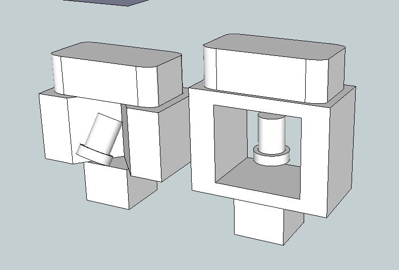
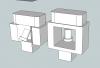
I got these prototypes done from ponoko (no photo as my house is too dark) My findings: - 8mm acrylic (the middle section in my pictures) costs too much to cut for this application - Version on left side creates shadows. The middle section that the LED shines through needs to extend around the sides of the top section. - The thin parts on the right hand version are too thin for 8mm acrylic - gets melted/bent. - 4.5mm arctic ice acrylic looks quite decent as the top section. Engraving went on the glossy side? I've emailed Ponoko to ask if that was a mistake. I'm going to investigate an assembly from 2 or 3mm acrylic similar to some of Sasha's creations.
-
Is the contact resistance of a switch important? In BLM? I'm looking at the ALPS SKPG series: http://www.alps.com/products/WebObjects/catalog.woa/E/HTML/Tact/SurfaceMount/SKPG/SKPG_list.html (Nice tactile push feeling, but low noise) It's 1kOhm vs. 50-100mOhm for the other switches I've looked at. Thanks :)
-
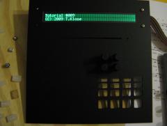
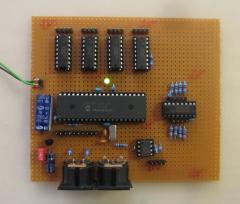
From the album: findbuddha's midibox adventures
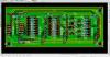
Already found several errors :frantics: -
I think the labels on the DOUT PCBs are mirrored to what the Core numbers them, that's why the config file is mirrored to the PDF. There are 4 SRs per DOUTx4, SR 11 is the 3rd SR on the 4th DOUTx4. From MBSEQ_HW.V4: 0 = disabled. You can make all of these selections match your hardware.
-
For the right hand (green LEDs), you'll get the first button press (green), you won't get the second button press (red), you'll get half of the third button press (should be orange but you'll get green as it's just a single LED)
-
That would be the expected behaviour, as per the readme. As you're using single colour LEDs, you won't see (for example) the red LEDs turn green (first button press) or orange (third button press).
-
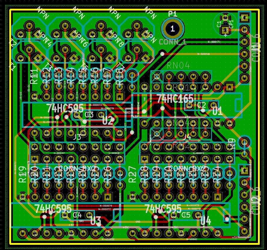
On Wilba's PCB, the 74HC595 in question: 4 of the pins are connected to 2 resisters in parallel eg. DOUT12 and DOUT12A