findbuddha
-
Posts
267 -
Joined
-
Last visited
Content Type
Profiles
Forums
Blogs
Gallery
Everything posted by findbuddha
-
I hurry for myself too :) Soldering complete. There are some minor issues that I should be able to sort out but I won't get to troubleshoot them until the weekend. For now, I offer merely a pic in the gallery. :flowers: One lesson learned: double check schematics before getting boards printed!
-
From the album: findbuddha's midibox adventures
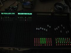
Let there be light :sorcerer: A few bugs to sort out with the BLM yet, but no 'systemic' problem like with the SEQ switches. -
This is the datasheet I've used for these switches http://www.alps.com/...t/SKPG/SKPG.PDF To the best of my knowledge this is the correct one. Hawkeye, I think maybe you'd be better off thinking of this as a 3 or 4 layer design. Cost will increase but I think it's the only way to achieve the compactness you're looking for. Still haven't finished soldering mine. Back at university now. Hopefully get done on wednesday.
-
I don't know the answer to your question about Ohms, but try searching for RS60N11M9A0 on mouser.com
-
It might be more feasible with the Core32 version, perhaps with a little coding effort though. Multiple MIDI ports over USB could be used. The main limitation (I think) will be a shortage of inputs available on a single core, depending on how many controls you want to pack in. You'll also need to use the MF_v3 module (not yet available from SmashTV) if you want touch sensitivity with faders on Core32. :)
-
I've been happy enough with KiCAD. Free! Woooo. It also has a nifty ability to append .brd files together for cheaper manufacturing at eg. gold phoenix. And easy access to the Freerouting.net router, which I find very user friendly to route traces manually. Initial test with my BLM PCBs revealed a silly error, but fortunately it is correctable with a simple but time consuming cable modification. 1st two buttons/LEDs seem to work as expected. I hope to have the rest completed today/tonight.
-
The button spacing on my BLM and Seq PCBs is 19mm horizontal, 14mm vertical. I haven't spent much time using it yet but so far I'm happy with the spacing on the Seq. You may find it very difficult to route the traces from the Scalar sections to the matrix with a 2 layer board. Also, you need to factor in possible front panels + button caps, and maybe check whether the vertical separation between each row is sufficient (visually with the LEDs.) And anchoring the whole thing to a case. I hope to have initial testing done on my BLM PCBs done in the next few days and will be happy to share - hopefully no mystery problems like with my Seq PCB. :)
-
I can confirm how nice those buttons are. Soft feel, quiet. And easier to solder than the 4 pin through hole types. AFAIK there's nothing preventing this happening now. The 16x16 app already exists for MIOS32. The main difficulty implementing a 'simple' PCB is fitting all the BLM_SCALAR components on it.
-
From the album: findbuddha's midibox adventures
My switch matrix still isn't working though :frantics: -
From the album: findbuddha's midibox adventures
-
 Avijjâ paccayâ sankhârâ - Ignorance conditions kamma formations. Sankhârâ paccayâ viññanam - Kamma formations condition consciousness. Viññanam paccayâ nâmarûpam - Consciousness conditions mind-matter. Nâmarûpa paccayâ salâyantanam - Mind-matter conditions six-sense bases. Salâyantana paccayâ phasso - Six-sense bases condition contacts. Phassa paccayâ vedanâ - Contacts condition feelings. Vedanâ paccayâ tanhâ - Feelings condition craving. Tanhâ paccayâ upâdânam - Craving conditions clinging. Upâdâna paccayâ bhavo - Clinging conditions becoming (or action). Bhava paccayâ jâti - Becoming conditions birth. Jâti paccayâ jaramaranam soka parideva sukkha domanassu-pâyâsâ sambhavanti Evametassa kevalassa dukkha-khandassa samudayo hoti - Birth conditions old age, death, grief, lamentation, pain, depression and despair. Thus the entire mass of suffering arises.
 -
concept for my controller, extremely new at this
findbuddha replied to Michael S's topic in MIDIbox HUIs
You need to be a bit clearer about what you actually want your midibox to do. What software are you going to use it with? :) -
There's http://svnmios.midibox.org/ and http://ucapps.de/ for starters if you haven't found them already. There are lots of tutorials in the SVN, and TK's code is clear and well commented.
-
concept for my controller, extremely new at this
findbuddha replied to Michael S's topic in MIDIbox HUIs
Seems you might actually want a sequencer with some knobs and faders for tweaking, levels, etc. Check some of these videos to see if the MBSeq project might be what you're looking for: The project page is here: http://ucapps.de/midibox_seq.html Additional knobs and faders are possible if I recall correctly, but probably better added on a separate core. -
concept for my controller, extremely new at this
findbuddha replied to Michael S's topic in MIDIbox HUIs
Here are some options for your illuminated buttons: http://shop.lividins...om/builder.html http://www.sparkfun.com/categories/145 There are also some individual illuminated buttons available but they're often horribly expensive. As for the Core, I'd personally choose a Core32 module. Even if you're not a programmer you'll appreciate the USB connection, which the Core8 does not have. I'm currently building up a case I've had laser cut at Ponoko. I can highly recommend them. The design can be made using all free software ie. Sketchup and Inkscape. Are your knobs potentiometers or rotary encoders? As for things you've missed..... connectors, wire, pot caps, fader caps, screws, soldering iron etc.... Not quite sure what you want it to do, but it's not part of the midibox64 app, unless your sequencer can output a midi signal each beat. Are you using this for Ableton live? if so, you may want to check out -
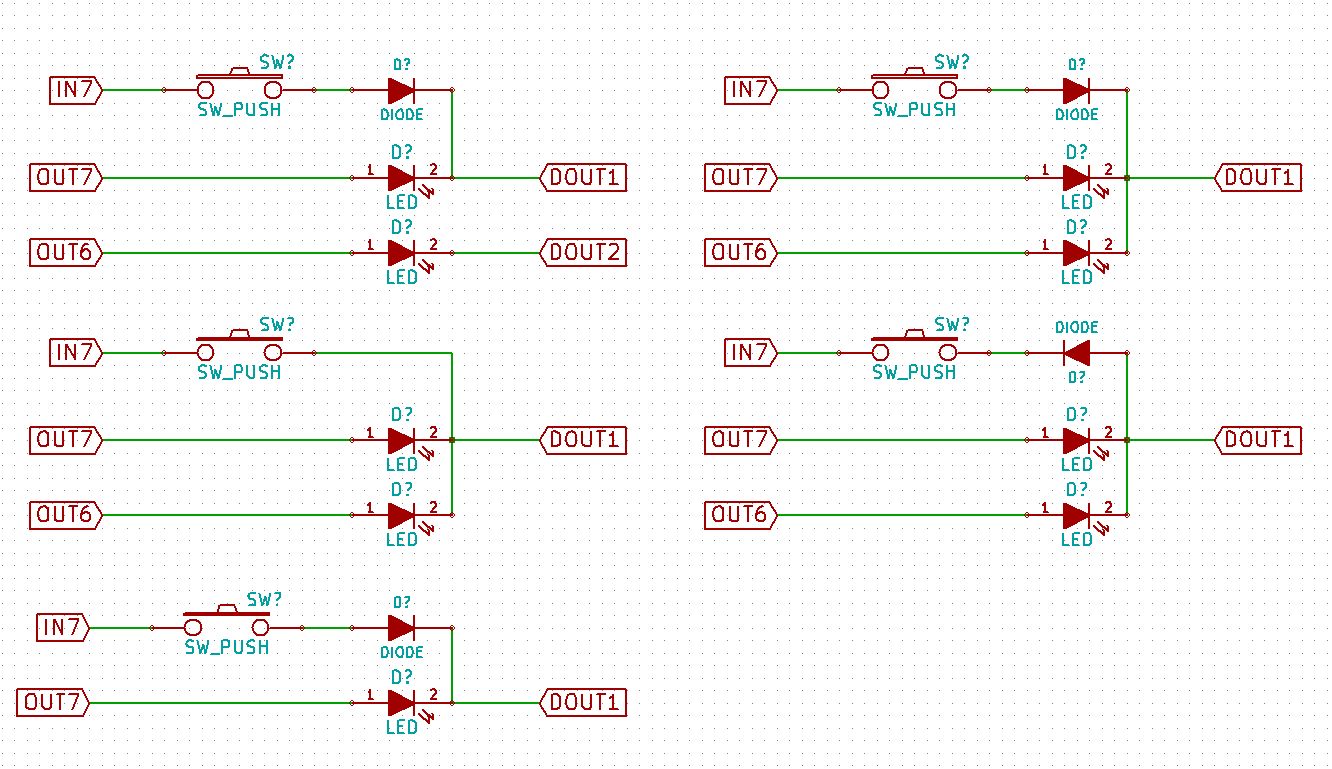
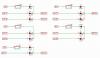
I've done some testing on a breadboard, and confirmed/extended the results with my PCB. The shift registers are not on the control surface so this should be a valid test. I've attached an image of the circuits I tested. The circuits on the left worked as intended. The circuits on the right did not work. I don't get why it worked without a diode for the switch? (The numbers in the image are just for example, I have verified that my assignments seem to point to the correct LEDs and switches) Thanks :) And my config file: ################################################## # Setup File for Wilba's Frontpanel # $Id: MBSEQ_HW.V4 951 2010-03-07 17:49:12Z tk $ ################################################## ################################################## # MIDI Remote Keyboard Function ################################################## # The note number which activates the remote function # 96 = C-7 (by some MIDI monitors displayed as C-8) # 0 disables the remote keyboard function MIDI_REMOTE_KEY 96 # The CC number which activates the remote function # (e.g. to control it with a footswitch) # Allowed numbers: 1-127 for CC#1..CC#127 # 0 disables the function (default) MIDI_REMOTE_CC 0 ################################################## # Shift Register Setup ################################################## # number of first and second DOUT shift register used for GP LEDs GP_DOUT_L_SR 3 GP_DOUT_R_SR 4 # DOUTs for Dual Color option: GP_DOUT_L2_SR 0 GP_DOUT_R2_SR 0 ################################################## # Optional BLM Matrix ################################################## # set this value to 1 if each track has its own set of 16 LEDs to display unmuted steps and current sequencer position # or if you are using a button/led matrix for misc. button/LED functions BLM_ENABLED 1 # define the shift registers to which the anodes of these LEDs are connected # Note: they can be equal to GP_DOUT_[LH]_SR, this saves two shift registers, but doesn't allow a separate view of UI selections BLM_DOUT_L1_SR 0 BLM_DOUT_R1_SR 0 # define the shift register to which the cathodes of these LEDs are connected # Note that the whole shift register (8 pins) will be allocated! The 4 select lines are duplicated (4 for LED matrix, 4 for button matrix) # The second DOUT_CATHODES2 selection is optional if LEDs with high power consumption are used - set this to 0 if not used BLM_DOUT_CATHODES_SR1 0 BLM_DOUT_CATHODES_SR2 0 # set an inversion mask for the DOUT shift registers if sink drivers (transistors) # have been added to the cathode lines # Settings: 0x00 - no sink drivers # 0xf0 - sink drivers connected to D0..D3 # 0x0f - sink drivers connected to D7..D4 BLM_DOUT_CATHODES_INV_MASK 0x00 # 0: no DUO colour LEDs are connected to the LED matrix (position marker inverts step LED) # 1: DUO colour LEDs are connected to the LED matrix, second LED displays position marker # 2: Like option 1, but the first LED is turned off when the position marker activates the second LED BLM_DOUT_DUOCOLOUR 0 # define the shift registers to which the anodes of the "second colour" (red) LEDs are connected BLM_DOUT_L2_SR 0 BLM_DOUT_R2_SR 0 # set this to 1 if a button matrix is connected BLM_BUTTONS_ENABLED 1 # set this to 1 if these buttons should only control the "step triggers" (gate, and other assigned triggers) - and no UI functions BLM_BUTTONS_NO_UI 1 # define the DIN shift registers to which the button matrix is connected BLM_DIN_L_SR 0 BLM_DIN_R_SR 0 ################################################## # Additional 8x8 BLM as used for Wilba's Frontpannel ################################################## # set to 1 to enable 8x8 BLM driver BLM8X8_ENABLED 1 # to which shift register are the select lines connected? # Allowed values: 0 to disable, 1..16 to assign shift register BLM8X8_DOUT_CATHODES_SR 1 # set an inversion mask for the DOUT shift registers if sink drivers (transistors) # have been added to the cathode lines BLM8X8_DOUT_CATHODES_INV_MASK 0x00 # to which shift register are the LED anode lines connected? # Allowed values: 0 to disable, 1..16 to assign shift register BLM8X8_DOUT_LED_SR 2 # 0: no mapping of 8x8 LEDs # 1: enable GP LED -> 8x8 matrix mapping for Wilba's MB-SEQ PCB BLM8X8_DOUT_GP_MAPPING 1 # 8x8 matrix for misc. button functions BLM8X8_DIN_SR 1 ################################################## # CV and Gate/Trigger/Sync Setup ################################################## # define the AOUT interface which is connected to the core # 1: a MBHP_AOUT module # 2: up to 4 (chained) MBHP_AOUT_LC modules in 8/8 bit configuration # 3: a MBHP_AOUT_NG module AOUT_INTERFACE_TYPE 1 # additional gate triggers are available on common digital output pins of the # DOUT shift register chain - they are assigned to AOUT channel #16 (Note C-1, C#1, D-1, ...) # define the shift registers which should be used here (each provides 8 gates) # Note that SRs assigned to this function cannot be used as LED outputs (exclusive function) # Allowed values: 1-16, 0 disables the function, all other values invalid and not allowed DOUT_GATE_SR1 0 DOUT_GATE_SR2 0 DOUT_GATE_SR3 0 DOUT_GATE_SR4 0 DOUT_GATE_SR5 0 DOUT_GATE_SR6 0 DOUT_GATE_SR7 0 DOUT_GATE_SR8 0 # if set to 1, the DOUT "gates" will send 1mS pulses # useful for analog drums DOUT_1MS_TRIGGER 0 # should J5A/B/C outputs be enabled (0: no, 1: yes, 2: yes, but in open drain mode)? # - the 8 AOUT gates will be forwarded to J5A/B # - DIN sync clock will be forwarded to J5C:A0 # - DIN sync start/stop will be forwarded to J5C:A1 # - if open drain mode enabled (option 2), external pull-ups have to be connected to J5 pins # (advantage: pin levels can be pulled to 5V) # # NEVER USE THIS TOGETHER WITH ANALOG POTS - IT WILL CAUSE A SHORT CIRCUIT! J5_ENABLED 1 # pulsewidth of DIN sync clock (1..250 mS) DIN_SYNC_CLK_PULSEWIDTH 1 ################################################## # LED assignments to DOUT pins # SR = 0: LED disabled # SR = 1..16: directly forwarded to DOUT pin # SR = 17..24: forwarded to a 8x8 LED matrix ################################################## # SR Pin LED_TRACK1 0 0 LED_TRACK2 0 0 LED_TRACK3 0 0 LED_TRACK4 0 0 # SR Pin LED_PAR_LAYER_A 0 0 LED_PAR_LAYER_B 0 0 LED_PAR_LAYER_C 0 0 # SR Pin LED_BEAT 20 3 # SR Pin LED_EDIT 21 3 LED_MUTE 21 1 LED_PATTERN 22 3 LED_SONG 22 1 # SR Pin LED_SOLO 21 0 LED_FAST 22 2 LED_ALL 22 0 # SR Pin LED_GROUP1 0 0 LED_GROUP2 0 0 LED_GROUP3 0 0 LED_GROUP4 0 0 # SR Pin LED_TRG_LAYER_A 0 0 LED_TRG_LAYER_B 0 0 LED_TRG_LAYER_C 0 0 # SR Pin LED_PLAY 17 2 LED_STOP 18 2 LED_PAUSE 18 0 LED_REW 19 0 LED_FWD 17 0 LED_LOOP 0 0 LED_FOLLOW 0 0 # SR Pin LED_EXIT 24 2 LED_SELECT 23 0 LED_MENU 23 2 LED_SCRUB 20 0 LED_METRONOME 19 2 LED_RECORD 0 0 LED_UTILITY 19 1 LED_COPY 23 3 LED_PASTE 23 1 LED_CLEAR 24 1 # SR Pin LED_STEP_VIEW 21 2 LED_PAR_LAYER_SEL 0 0 LED_TRG_LAYER_SEL 0 0 LED_TRACK_SEL 0 0 # SR Pin LED_TAP_TEMPO 0 0 LED_TEMPO_PRESET 0 0 LED_EXT_RESTART 0 0 # SR Pin LED_DOWN 20 1 LED_UP 19 3 # SR Pin LED_MORPH 0 0 LED_MIXER 0 0 LED_TRANSPOSE 0 0 ################################################## # Button assignments to DIN pins # SR = 0: Button disabled # SR = 1..16: directly triggered from DIN pin # SR = 17..24: triggered from a 8x8 button matrix ################################################## # SR Pin BUTTON_DOWN 20 6 BUTTON_UP 19 4 BUTTON_LEFT 0 0 BUTTON_RIGHT 0 0 # SR Pin BUTTON_SCRUB 20 7 BUTTON_METRONOME 19 5 BUTTON_RECORD 0 0 # SR Pin BUTTON_STOP 18 5 BUTTON_PAUSE 18 7 BUTTON_PLAY 17 5 BUTTON_REW 19 7 BUTTON_FWD 17 7 BUTTON_LOOP 0 0 BUTTON_FOLLOW 0 0 # SR Pin BUTTON_MENU 23 5 BUTTON_SELECT 23 7 BUTTON_EXIT 24 5 # SR Pin BUTTON_TRACK1 0 0 BUTTON_TRACK2 0 0 BUTTON_TRACK3 0 0 BUTTON_TRACK4 0 0 # SR Pin BUTTON_PAR_LAYER_A 0 0 BUTTON_PAR_LAYER_B 0 0 BUTTON_PAR_LAYER_C 0 0 # SR Pin BUTTON_EDIT 21 4 BUTTON_MUTE 21 6 BUTTON_PATTERN 22 4 BUTTON_SONG 22 6 # SR Pin BUTTON_SOLO 21 7 BUTTON_FAST 22 5 BUTTON_ALL 22 7 # SR Pin BUTTON_GP1 21 0 BUTTON_GP2 21 1 BUTTON_GP3 22 0 BUTTON_GP4 22 1 BUTTON_GP5 23 0 BUTTON_GP6 23 1 BUTTON_GP7 24 0 BUTTON_GP8 24 1 BUTTON_GP9 20 0 BUTTON_GP10 20 1 BUTTON_GP11 19 0 BUTTON_GP12 19 1 BUTTON_GP13 18 0 BUTTON_GP14 18 1 BUTTON_GP15 17 0 BUTTON_GP16 17 1 # SR Pin BUTTON_GROUP1 0 0 BUTTON_GROUP2 0 0 BUTTON_GROUP3 0 0 BUTTON_GROUP4 0 0 # SR Pin BUTTON_TRG_LAYER_A 0 0 BUTTON_TRG_LAYER_B 0 0 BUTTON_TRG_LAYER_C 0 0 # Following button functions are usually assigned to Fx # buttons, or to dedicated (labeled) buttons # In Wilba's frontpanel layout: # F1 is located at SR 19 Pin 3 # F2 is located at SR 18 Pin 2 # F3 is located at SR 18 Pin 3 # F4 is located at SR 17 Pin 2 # and there are dedicated buttons for Copy/Paste/Clear/Utility/StepView # SR Pin BUTTON_TEMPO_PRESET 18 4 BUTTON_PAR_LAYER_SEL 24 4 BUTTON_TRG_LAYER_SEL 24 3 BUTTON_TRACK_SEL 24 2 # SR Pin BUTTON_UTILITY 19 6 BUTTON_COPY 23 4 BUTTON_PASTE 23 6 BUTTON_CLEAR 24 6 # SR Pin BUTTON_STEP_VIEW 21 5 # SR Pin BUTTON_TAP_TEMPO 20 5 BUTTON_EXT_RESTART 0 0 # SR Pin BUTTON_MORPH 0 0 BUTTON_MIXER 0 0 BUTTON_TRANSPOSE 0 0 ################################################## # Button behaviour # 0: active mode so long button pressed # 1: pressing button toggles the mode ################################################## BUTTON_BEH_FAST 1 BUTTON_BEH_ALL 1 BUTTON_BEH_SOLO 1 BUTTON_BEH_METRONOME 1 BUTTON_BEH_LOOP 1 BUTTON_BEH_FOLLOW 1 BUTTON_BEH_SCRUB 0 BUTTON_BEH_MENU 0 BUTTON_BEH_STEP_VIEW 0 BUTTON_BEH_TRG_LAYER 0 BUTTON_BEH_PAR_LAYER 0 BUTTON_BEH_TRACK_SEL 0 BUTTON_BEH_TEMPO_PRESET 0 ################################################## # Special Behaviour of ALL button # 0: only parameter layers are modified by ALL function # 1: trigger and parameter layers are modified by ALL function ################################################## BUTTON_BEH_ALL_WITH_TRIGGERS 0 ################################################## # Encoder Functions # SR = 0: encoder disabled # SR = 1..16: DIN assignment # Types: NON_DETENTED, DETENTED1, DETENTED2, DETENTED3 ################################################## # SR Pin Type ENC_DATAWHEEL 0 2 DETENTED2 # the speed value for the datawheel which is used when the "FAST" button is activated: ENC_DATAWHEEL_FAST_SPEED 3 # SR Pin Type ENC_GP1 4 6 DETENTED2 ENC_GP2 4 4 DETENTED2 ENC_GP3 4 2 DETENTED2 ENC_GP4 4 0 DETENTED2 ENC_GP5 5 6 DETENTED2 ENC_GP6 5 4 DETENTED2 ENC_GP7 5 2 DETENTED2 ENC_GP8 5 0 DETENTED2 ENC_GP9 6 6 DETENTED2 ENC_GP10 6 4 DETENTED2 ENC_GP11 6 2 DETENTED2 ENC_GP12 6 0 DETENTED2 ENC_GP13 7 6 DETENTED2 ENC_GP14 7 4 DETENTED2 ENC_GP15 7 2 DETENTED2 ENC_GP16 7 0 DETENTED2 # the speed value for GP encoders which is used when the "FAST" button is activated: ENC_GP_FAST_SPEED 3 # Auto FAST mode: if a layer is assigned to velocity or CC, the fast button will be automatically # enabled - in other cases (e.g. Note or Length), the fast button will be automatically disabled ENC_AUTO_FAST 1
-
Thanks both for your help. I suspect I have eliminated my previous configuration file errors, but the problem remains. When I try that debugging option I get the intended output for buttons that haven't been disabled by >1 LEDs, but no message comes in MIOS Terminal for the buttons disabled by the LEDs. Would this be symptomatic of switch diodes around the wrong way? As far as I can tell I've got it correctly, and I'd rather not start desoldering if that's not likely. :)
-
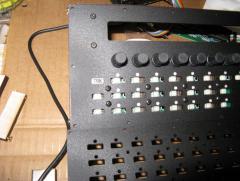
I'm testing my Seq PCB prior to soldering all the LEDs in place, and I've noticed a strange issue. All the buttons work fine, unless more than 1 LED in the BLM8x8 column (select line, cathode - not sure of the correct terminology) is lit. Repeatedly pressing will occasionally get a 'hit'. It's completely reliable when <=1 LED is lit for the column. The PCB is of my own creation, based largely on Wilba's Seq PCB. Thanks :) :sorcerer:
-
dont even know where to start :( plz help
findbuddha replied to markrodgers11's topic in MIDIbox User Projects
1st step is patience and a lot of reading both in this forum and at ucapps.de After that you'll have a bit more idea about what the midibox platform is, and what you actually want to build. If you really just want a small, cheap midi controller, you may be better off looking at (for eg.) the Korg NanoKontrol, or Novation Nocturn :) -
Core32 not recognised by OS (WinXP)
findbuddha replied to latigid on's topic in Testing/Troubleshooting
I think this was it: -
I got it to build by modifying the Makefile using one from SVN as example, but this may not be what you want (wrong processor). PROCESSOR = p18f452 LKR_FILE = $(MIOS_PATH)/etc/lkr/$(PROCESSOR).lkr project.zip
-
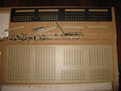
Thanks all for your support! It is a bit intimidating - not sure where to begin now :frantics: Still waiting for some screws to arrive. Hawkeye, I have designed a BLM PCB. I haven't had the big one manufactured yet, but I've got the small one (seen on bottom right of panel). This will be my test to see if it is working properly. I intend to share all my design files once the project is 'complete enough' and I've found any errors, but anyone who wants a look at a specific part before then is welcome. Just send a PM.
-
From the album: findbuddha's midibox adventures
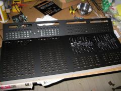
For MBSeq + BLM16x16 + my own mixer section with encoders, motorfaders and buttons. It's a continuous wide panel to ease fitting PCBs inside, and as it will sit as a single unit on top level of my 2-tiered keyboard stand.:sorcerer: -
Noone's asking you to go away, and neither has anyone suggested that your ideas are invalid. People have in the past signed up on the forum, demanded to be able sell TK and other's work, then become indignant when told they may not. You may guess that it's not the best way to introduce yourself around here. Please, if you are interested in contributing your knowledge, stick around. Buy a Core32 kit, or even get a populated LPCXpresso board here: http://www.embeddeda...lpc1769_xpr.php For someone of your skillset this shouldn't be a barrier to entry - if you genuinely want to participate here. Things move slowly around here sometimes. :thumbsup: