grizz
-
Posts
201 -
Joined
-
Last visited
Content Type
Profiles
Forums
Blogs
Gallery
Everything posted by grizz
-
Question about hooking up KS0107/KS0108 GLCD
grizz replied to grizz's topic in Testing/Troubleshooting
Sooooooooo, I just hooked up CS1---->J28:SDA and CS2---->J28:Vd and the GLCD appears to work fine... prints the bootloader message upon "reset" and then prints the Midibox_NG message, followed by "ready". I'm definitely following the mbhp_core_lpc17 schematic correctly... is the notch on J28 on that schematic maybe backword ? If you look at J28 with the notch on the left CS2 is connect to the 2nd pin from the top and CS1 is connected to the middle pin... If that helps clarify... once the bootup screen is through and "ready" is displayed properly in the upper right hand corner when I hit the "exit" and "shift" keys the text on the next menu pages is somewhat jumbled... Some words are printed correctly but with nonesense printed around them... is this because I have CS2 connected to Vd, or is this something I can start teaching myself to fix in the .NGC file? I feel like I'm close... but if not I will wait on the oscilloscope and test the J28:SDA and SC pins... -
Question about hooking up KS0107/KS0108 GLCD
grizz replied to grizz's topic in Testing/Troubleshooting
I do have access to a scope... My friend is going to be keeping his scope and bench PSU at my workstation for a bit, so I can take some measurements once he drops them off... Just to confirm, I should not be using the KS0108_invcs, correct? I should instead be using ks0108? I'm going to be busy for the next couple of hours, but when I get back I'll go back over all my connections to the GLCD and make sure again that they are all correct... Thanks for the help!! alex -
Question about hooking up KS0107/KS0108 GLCD
grizz replied to grizz's topic in Testing/Troubleshooting
Yes, nothing at all happens when connected to those... I tried both the KS0108_invcs and the ks0108... Thanks, Alex PS, When I added the 10k trimpot, I left VO on J15A open... is that ok? -
Question about hooking up KS0107/KS0108 GLCD
grizz replied to grizz's topic in Testing/Troubleshooting
Tried all three project.hex and none worked... I did hook up CS1 and CS2 to J5A, A4 and A5, and what I got was text in the top 1/3 of the screen and almost solid black in the bottom 2/3 of the screen after that the bottom stayed black until I left it off for a minute or two... thanks! alex -
Question about hooking up KS0107/KS0108 GLCD
grizz replied to grizz's topic in Testing/Troubleshooting
One more thing that I noticed while looking at a topic today... I have a V1.0 board that I got awhile back, and I noticed in another topic that there is an incorrect trace on J15... I didn't know about this, could it be the problem? I couldn't find any documentation when I searched for this problem.... a -
Question about hooking up KS0107/KS0108 GLCD
grizz replied to grizz's topic in Testing/Troubleshooting
Ok, after failing to figure out how to create a new album for the pictures I just added them to my MBFM one... I'll delete them when we're done... sorry! - both CS inputs are connected to Ground (J28:Vs) - both CS inputs are connected to 3.3V (J28:Vd) - both CS inputs are connected to 5V (J2:Vd) - CS1 is connected to Vs and CS2 is connected to 5V - CS1 is connected to 5V and CS2 is connected to Vs Thanks again for all the help!!! Cheers, Alex -
Question about hooking up KS0107/KS0108 GLCD
grizz replied to grizz's topic in Testing/Troubleshooting
Ok, so I tried the ks0108_invcs, and still nothing... I don't know if this helps, but when I connect the LCD to J5 and jumbled text prints, and then connect to the correct J28 pins and reset the text doesn't change or go away during or after reset... Could the J28 pins not be activated? Thanks!! alex -
Question about hooking up KS0107/KS0108 GLCD
grizz replied to grizz's topic in Testing/Troubleshooting
Ok, so I wired up a 10k trimpot, and now I get something! J28 doesn't seem to work though, so I used J5B, A4 and A5, which give me jumbled text: "is oader is oader :-) -date! :-) _date!" That is not exactly what the text looks like, but close. I'm guessing it has to do with CS pin 1 and 2, and where they are being hooked up. The correct pins on J28 don't produce and text at all, and all the pins on J5A and J5B(except Vs and Vd of course) give similar jumbled text. I am using: lcd_type 0x81 GLCD_KS0108 lcd_num_x 1 lcd_num_y 5 lcd_width 128 lcd_height 64 Is there something else obvious that I am missing? Cheers, Alex -
Question about hooking up KS0107/KS0108 GLCD
grizz replied to grizz's topic in Testing/Troubleshooting
Thanks TK!!! I'll wire up a 10k trimpot when I get home later... I read over that schematic, but missed te trimpot. I'm excited to get it functioning so I can continue teaching myself how to customize midibox NG!!! Cheers, Alex -
Question about hooking up KS0107/KS0108 GLCD
grizz replied to grizz's topic in Testing/Troubleshooting
Hi again... I haven't been able to get my GLCD to work yet, and have a couple of questions to make sure I'm not missing something important. 1. My understanding is that the only changes I need to make are in MIOS studio with just the bootloader installed. ie. Set LCD_TYPE, set LCD_num_x, etc. Is this true, or do I need to do edits and teach myself how to recompile 32-bit apps (I've only managed to teach myself how to compile for the PIC based core applications)? 2. This is related to question 1 I think... Are the SC and SDA on J28 set up to automatically work with the KS0108, do I have the correct pins, or do they need to be activated? Cheers, Alex -
Question about hooking up KS0107/KS0108 GLCD
grizz replied to grizz's topic in Testing/Troubleshooting
Thanks for the reply TK... I followed your instructions, and then uploaded the newest bootloader, and typed in the commands: lcd_type GLCD_KS0108 lcd_num_x 1 lcd_num_y 5 lcd_width 128 lcd_height 64 I also tried LCD_type GLCD_ks0108_INVCS to no avail Unfortunately the GLCD didn't display anything, other than the backlight... I switched back to my generic 2X16 LCD and retyped the commands to set the bootloader for the generic LCD, but now that doesn't work either... I get black bars on the 2X16 LCD briefly on startup before it goes blank... I tried reloading the bootloader to siwtch back to the generic LCD setup to no avail. I hooked the 2X16 LCD up to my SEQ V4 and it works fine, so it is something with the LPC... What am I missing? I really hope I didn't fry something on the LPC!!!! Haha, I always seem to figure things out 5 minutes after posting... The LCD_type wasn't changing because I wasn't entering the 0X00 ... I'll keep working on the GLCD and see if I can get it to work... Cheers, Alex -
Question about hooking up KS0107/KS0108 GLCD
grizz replied to grizz's topic in Testing/Troubleshooting
Here is the link: https://www.sparkfun.com/products/710 Thanks, alex -
I bought a GLCD from Sparkfun that uses the KS0107/KS0108 and has the negative voltage circuitry built on the board. I'm a little confused about hooking it up and making it work... Here is what I have got so far: GLCD ----a LPC 1 vd 2 vs 3 V0 4-11 D0-D7 12 J28:SDA 13 J28:SC 14 RS 15 RW 16 17 E 18 19 B+ There are only 2 CS lines as far as I can tell, but I am also confused about what to do with Pins 16 and 18 on the GLCD. 16 is D/I and 18 is VEE. Am I on the right track as far as hooking it up? Once I have it all hooked up properly I have gathered that I get it working with these commands in MIOS studio: lcd_type GLCD_KS0108 lcd_num_x 1 lcd_num_y 5 lcd_width 128 lcd_height 64 Thanks in advance for any help!! Cheers, Alex
-
Control surface PCB for 16 encoders/LEDrings Bulk Order
grizz replied to Fairlightiii's topic in Bulk Orders
Mine arrived in Portland Oregon today... Thanks for all the work!!! a -
Thanks Tim... Lets hope I didn't fry either of my AOUT_NG's ... I did some research, and either way I just learned a lot thanks to your heads up. cheers, alex
-
So, I stumbled across altitude's thread involving his AOUT_NG and core32 issues that were resolved with shortening the cable connecting the core and AOUT... Since my cable is much longer than his original non-working cable I'm going to try a shorter cable later. The odd thing is that it worked fine with my MB6582, but maybe there is some sort of different between the 8-bit core and the 32-bit core... Cheer, Alex
-
What I meant to say is that when I power on the 12volt supply to the AOUT_NG and use my multimeter to check conductivity between the GND pin and CV pins at J5 they are connected (bridged) ... the multimeter "beeps" This doesn't seem normal to me, but it happens to both of my AOUT_NG's, one of which has never worked with the SEQ V4, but worked fine with my MB6582. I haven't tried the test yet, but I will when I get off work later today. Yes. Thanks, Alex
-
Hey all, I have been trying to figure out why my AOUT_NG no longer works with my SEQ V4. To start I am running the newest version bootloader and SEQ OS. I have had this setup working with both my SEQ V4 and my old MB-6582 (sold). Here is my first question: When I power on my +-12 Volt power supply hooked up to the AOUT_NG, the ground and cv pins on J5 are bridged... Normal? I'm assuming not, but I can't for the life of me figure out why this is happening... I have removed the AOUT and PSU from their enclosure and disconnected the AOUT from the core32 so that the only connections are the 12v PSU and the AOUT... The PSU is outputting the proper power readings. Any ideas? I have two AOUT_NG's and have confirmed the same behavior with both. If this is normal I have some other problem, but I wanted to eliminate this as a possibility first. Thanks!
-
Hey there, I'm asking for permission to sell my MB-6582 with 8 8580's and an external SSM2044 filter in an aluminum box with an AOUT_NG, linking to the synth through the com port. I'm really torn about whether or not to sell it, but I don't use it much... If people want pictures shoot me a pm with your email and I'll send them over. I'm going to take offers and lean towards selling it to someone in the States, but I'm open to other continents. Cheers, Alex
-
One more question: What is the correct GP button to do a complete backup? I built an eight eeprom bankstick, so I have more memory than what the MB808 mainboard provides. I guess part of my problem is that I don't quite understand how the device ID works with backups... Thanks, grizz
-
Thanks TK!!!!
-
Hey all, Can someone lead me to the correct button combo to get to the screen to make patterns finish before switching to a new pattern? For example, if I am in A1 and switch to A2, A1 will play through to the last step before switching... Or if I am in A1 and switch between A and B they will continue to the last step before changing. I have been unable to figure this one out myself, even though it should be easy... Maybe I'm blind... Thanks. grizz
-
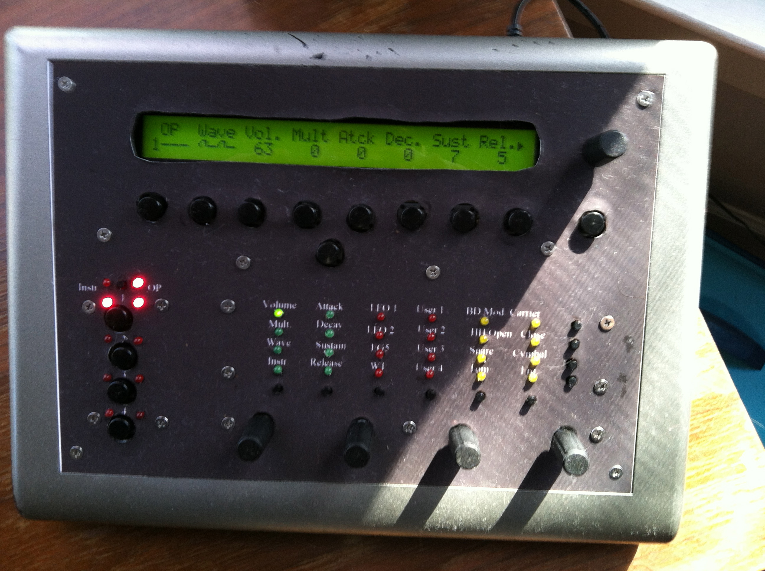
Hey all, I am selling my MBFM synth because I just never have gotten into the way it sounds. It uses the base PCB from the SammichFM with a custom control surface that I built on veroboard. The whole thing is housed in the case that is used for the MB-6582. I'm not sure what to ask for it, but looking briefly at what I spent on parts I think $350 is fair. I'll ship anywhere as long as paypal is used and you pay the shipping costs. I'll eat the % that paypal takes from the sale. It all works fine, but obviously it is sold as is, and if you want to buy it you should have enough knowledge to be able to work on it if something comes up. I attached a picture, but if someone wants more just let me know. I'm operating on the assumption that I don't need permission since this is a one off that I built for myself, but am selling because I never use it. Let me know if I'm wrong. Cheers, grizz
-
Yay!!! I'm interested in ~40 of the DR111 006/26 BLK and 20 of the DR111 006/26 GRY Cheers, grizz
-
Hey all, I built to many SSM2044 and SSM2164 boards that Seppoman designed and distributed. Here is what I have: 2 dual SSM2044 VCF boards built and tested WITHOUT SSM2044 chips 2 SSM2164 quad VCA boards built and tested WITH SSM2164 chips SOLD asking $70 for each built board. Although they are tested and work, you will have to calibrate them according to your needs. PM if you're interested. Cheers, grizz