

eptheca
-
Posts
373 -
Joined
-
Last visited
-
Days Won
16
Content Type
Profiles
Forums
Blogs
Gallery
Everything posted by eptheca
-
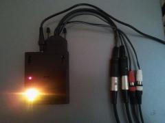
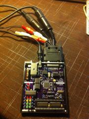
From the album: eptheca
My unit of Antichambre's MB-TIA project I just finished it last night I love it. Great little device, and with the Max/MSP patch it's really easy and fun to play with Merci beaucoup Antichambre :) a quick test http://www.flickr.com/photos/25935372@N06/8966415945/ -
Félicitation!
-
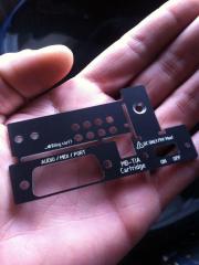
iPAD support and future Atari Pads support
eptheca commented on Antichambre's gallery image in Members Gallery
 Nice for the "Fruits" ;)
 -
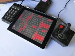
 This is going to make it really fun to play with
 -
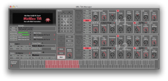
 An example of the level of detail in this project
 -
 Great PCB engineering! All that in such a small case. I thought the surface mount TQFP PIC was gona be a major PITA, but it was fairly easy :) Great for space challenging projects like this. Great work Antichambre!
 -
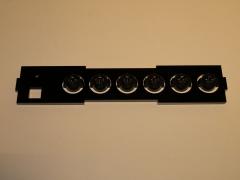
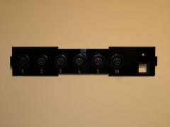
I have just finished 3 GM5's with 5 OUT and 1 IN I use W7 64, all 4 jumpers closed They all come up in Device Manager like this In SendSX like this and in Live like this Two GM5's are connected to a double USB 3.0 internal hub in my laptop, and the third to a single USB 2.0 internal socket in my laptop I am not sure why it comes up like it does, because it understands that it is 15 midi ports Also strange that port 1 on each unit comes up as Ploytec GM5, and not MIDIIN 1/6/11 At least I can use all the 15 ports, even if the names are a bit strange I will try to connect them to one HUB later, and see how that works
-
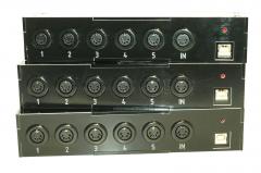
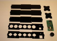
From the album: eptheca
Finished all 3 today :) Looking forward to replace my M AUDIO Midisport's -
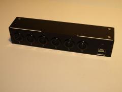
From the album: eptheca
-
From the album: eptheca
-
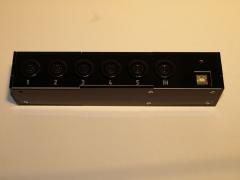
From the album: eptheca
-
From the album: eptheca
-
From the album: eptheca
-
 WOW! That's what I call a Midibox. Beautiful piece of equipment Very inspiring
 -
OK, thanks, yes see your point :) I'm building it with 5 OUT, but only 1 IN, do I need to ground the other IN pins? I am using the small GM5 pcb
-
I am leaving out the EEPROM does this mean I can leave out resistors R14 and R15 and cap. C4 as well?
-
What about the 220 ohm resistor between pic's TX and MIDI OUT?
-
thanks nILS I thought I had read that somewhere, but I needed to get it confirmed by a Guru :)
-
I'm building a MB64 controller for a synth. The synth is controlled with a Teensy ( similar to arduino) ATmega 32U4 I'm sending MIDI from my sequencer to the MB64 that merges the notes from the sequencer and the CC data from the pots connected to the Core My question: Do I need another optocoupler circuit between the Core and the Teensy? Or can just connect the PIC's TX to the Teensy RX? They are both powered by the same 5V circuit It just seams a bit "overkill" with the MIDI OUT resistors + MIDI IN circuit between them when they are powered by the same source.
-
SELLING: ALPS Motorfaders, ALPS Encoders, Midibox CV, GM5 Interfaces, etc.
eptheca replied to snykehd's topic in Fleamarket
I would like the 3 GM5 with chips please :) email sent as well -
Hi Thorsten, I changed this code in the mb64_buttons.inc file: ;; (button value stored in TMP1) MB64_BUTTON_OnOnly ;; when on: send button value defined in dump ;; when off: send nothing BRA_IFSET TMP1, 0, ACCESS, MB64_BUTTON_NotifyChangeEnd ;; turn off SR1 8 LEDs SET_BSR MB64_BUTTON_VALUES_SR0+0 setf MB64_BUTTON_VALUES_SR0+0 SET_BSR MB64_BUTTON_VALUES_SR0+1 setf MB64_BUTTON_VALUES_SR0+1 ;; save status of button rcall MB64_BUTTON_Hlp_SaveStat rgoto MB64_BUTTON_Send I found a post on the forum that suggested this Since I have no clue about programming, I don't understand what it does really, I just edited the code in the file. If I have to program a new MIOS application in C, I think I will have to let it go It looks like Lemonhorse's MB AY/YM V2 has button/LED handling like I am after, but I guess that is a separate MIOS application as well Thanks for the direction Best regards Halvor
-
I have built a MB64 to control a synth. I have a problem with the LED's This is what I am trying to achieve: The top 8 buttons are onOnly buttons, and the LED for each button light up when it is pressed, when another of the 8 buttons is pressed, the LED for that buttons lights up, and the other LED turns off. The 3 bottom left buttons are toggle buttons, the LED for that button lights up when it is pressed, and turns off when it is pressed again The 4 bottom right buttons are onOnly buttons, and the LED for each button light up when it is pressed, when another of these 4 buttons is pressed, the LED for that buttons lights up, and the other LED turns off. What happens now is that the 3 groups of buttons/LED's affect each other You can see the problem in this video YouTube Video I would really appreciate some help with this
-
I was going to use these for my project only 20 Euro for 20 :) http://www.ebay.com/itm/4-Sequential-Circuits-Momentary-Tact-Led-Switches-PB86-/120731587538?pt=LH_DefaultDomain_0&hash=item1c1c29d3d2#ht_1027wt_1065 They are of course not E-Switch, but for the 1/4 of the price maybe they will do the job
-
thanks guys Yes I cut them in half for space, just needed the 2 first shift registers
-
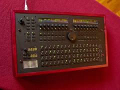
Hi everybody, Just finished building my controller for a YM2149 synth, and thought I'd share it with you Also cased in an old Sinclair ZX Spectrum + 128 case ( calm down - again just an empty case) Reused the buttons and modified them with LED's to make them look like Roland/ Sequential Circuits buttons from 80's synth's and drum machines The control panel is laser cut &engraved in a black&white acrylic. It is very similar to lemonhorse's MB AY (YM), but uses an Atmega328 module from Wil Lindsay at straytechnologies.com I got a while back http://www.straytech...m_mini-modding/ The control is done by the Core, DIN and DOUT modules from Smash TV I have a problem with the LED's so if any of you can help me with some Assembler code I would be very greatful Have a great weekend everybody, and thanks for the inspiration from all your projects :)
