Hawkeye
-
Posts
3,636 -
Joined
-
Last visited
-
Days Won
36
Content Type
Profiles
Forums
Blogs
Gallery
Everything posted by Hawkeye
-
Just finished my MB-658s but issues with 6581 chips
Hawkeye replied to Rave-TZ's topic in MIDIbox SID
did you try with fewer sid chips, maybe a psu problem when fully loaded? try with two 6581 in 1 and 2... -
Just finished my MB-658s but issues with 6581 chips
Hawkeye replied to Rave-TZ's topic in MIDIbox SID
Have you measured voltages without SIDs plugged in, as described in TKs build document? If so, you could move the 8580s to 1 and 2 (set to 9v before!) etc and test the output circuits. It is normal that 6581s get warmer than 8580s. You can add passive heatsinks (see my photo tut for parts link) if you feel uncomfortable about it. -
Michael, nice idea... what are your thoughts about "stuck" keys and general lifespan for a 256+ button matrix? Bilderbuchi, i guess the place may be needed for other switches, at least if Michael is going for a really tiny BLM. I am still pondering on the latex membrane idea, cheap transparent rubber feet for the buttons... and bicolor SMD LEDs next to those really nice tactile switches. Greets, Peter
-
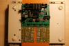
Step 8: Connecting The Power Supply and Powering On for the First Time :) Parts Used: Core32 Module (from step 5) MBSeq PSU (from step 2) 1541 power socket (from step 1) 1541 serial data cable (used as power cable) 5-pin PCB Interconnector plug, jack and cable (e.g. from Reichelt) 2-pin SIL housing and headers (power connector to J2 of the Core32 PCB) (e.g. from Mouser) A few centimeters of slightly-thicker-than-ribbon-wire wire A multimeter Your favorite soldering equpiment Description: * Unscrew the lower MIDI connector backplane and solder all components, so that they won´t fall off (photo 1). * Now plug in the MBSeq PSU from step 2, flick the power switch and measure the header pins with your multimeter switched to AC voltage measurement. You should be able to determine two GND pins, two +5V pins, one +12V and one -12V pin. * Solder the connections between the power socket and the power switch as depicted in photo 2. Attach to one +5V pin and one GND pin. * Add a 5-pin PCB interconnector header as visible in photo 3. * Now solder the connections from the power switch to two pins of the 5-pin PCB interconnector. Once again, use your multimeter to measure which of the pins is +5V and which is GND, when powered on. Plug in the interconnector plug and connect to J2 of the Core32. You can use a two-pin PCB-interconnector for that or SIL headers and cases. * If you want to test, you can temporarily crimp a LED in a 2-PIN SIL housing and flick the switch. If the LED flashes three times and then stays on, the Core is alive and you did well - have a cold beverage to celebrate :-). Note: Using the slightly-thicker-than-ribbon-wire wire for the power rails is probably pure insanity and may not be necessary...
-
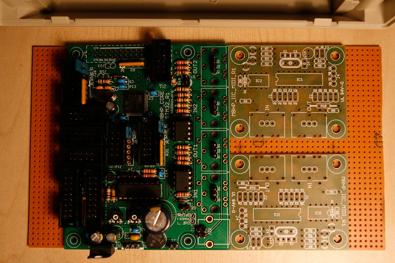
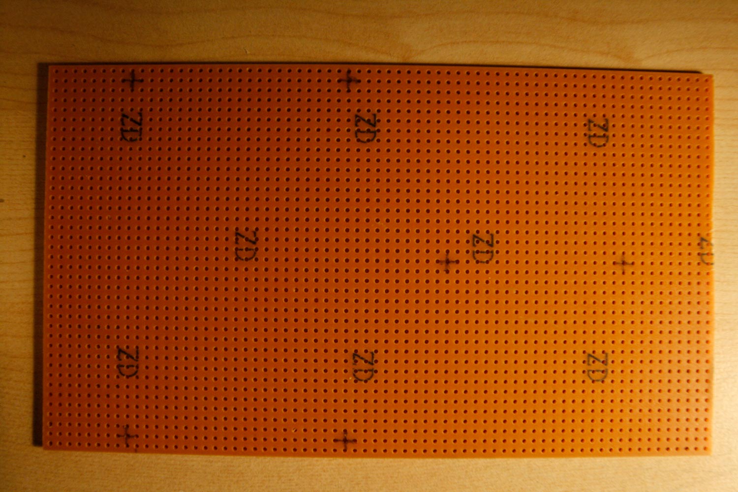
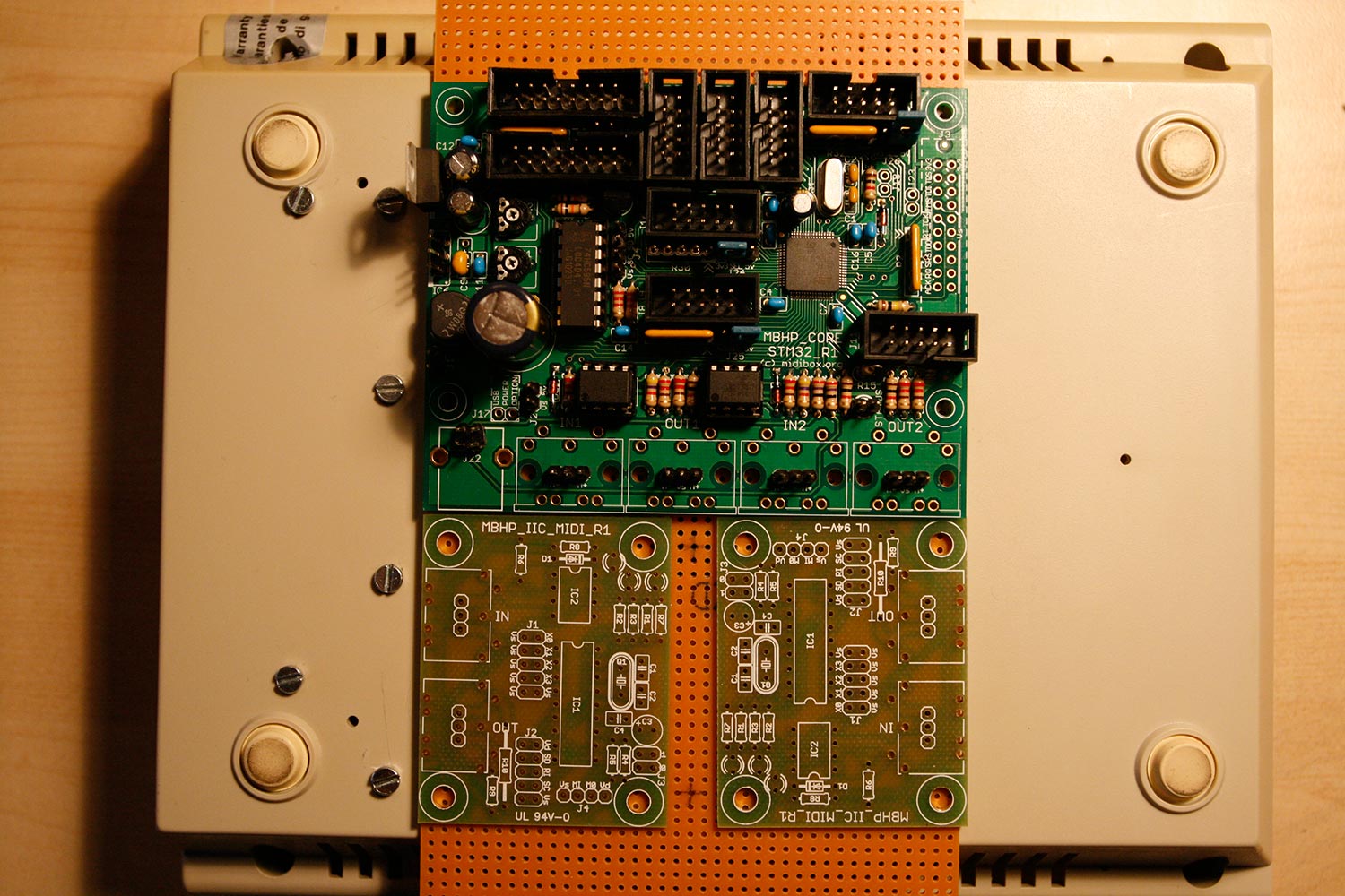
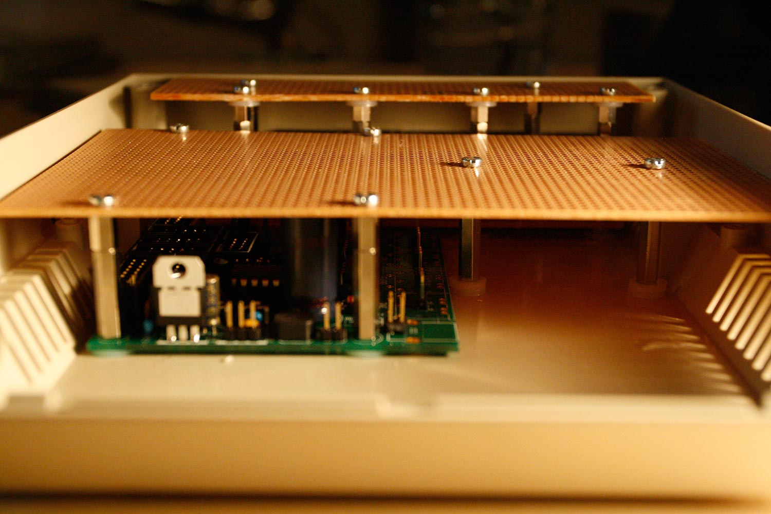
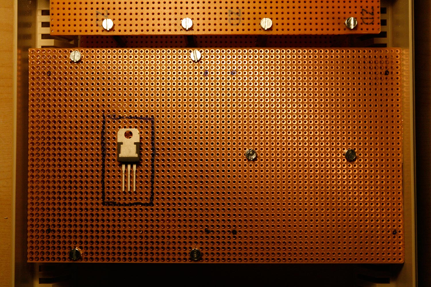
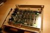
Step 7: Core Case Works: Prepare for Core32 and the AOUT_NG Module Parts Used: 10x20cm Vector board (any electronics store or Reichelt) Core32 Module (from step 5) 4x IIC MIDI PCB (AVI Showtech) 1x AOUT_NG PCB (AVI Showtech) 12pcs M3 Nylon washer (same as in step 6) 6pcs M3 20mm hex standoffs (any mechanical/electronics store or Reichelt) 6pcs M3 8mm hex standoffs (any mechanical/electronics store or Reichelt) 4pcs M3 5mm hex standoffs (from step 6) 12pcs M3 12mm screws (from step 6) 4 pcs M3 8mm screws (any electronics store or Reichelt) 8 pcs M3 nut (from step 6) Dremel tool with cutting wheel Bench drill or hand drill with 2mm, 3mm and 4mm drills Mechanical pencil (0.5mm) Description: * Using the dremel, create a vector board with size 100mm x 175mm * Place the core and two MIDI modules on the vector board as shown in photo 1. Mark the six standoff zones depicted as crosses in photo 2. * Turn over the 1541 bottom case and lay the prepared vector board on top, aligning it as shown in photo 3. Note: Take your time aligning... make sure, that the vector board, as well as the modules will fit in the case from the other side as depicted in the following pictures. * Mark the six drill spots with a mechanical pencil, make sure not to move the vector board while marking :-). * Drill the case, first with a 2mm, then with a 3mm drill (photo 4). In the most unlikely event that something does not fit, you can use 4mm drills to create more movement room for the screws. * Drill the vector board, first with a 2mm, then with a 3mm drill. * Hold your breath and install, inserting a 12mm screw from the back, adding a nylon washer, adding the Core32 module, adding 20mm standoffs. The two right standoffs require two nylon washers to compensate for the thickness of the Core32 PCB. Attach the upper vector board with 12mm screws from the top and 8mm hex standoffs. See photo 5. Fits neatly :-). * Mark additional drilling holes and the cutout zone for cable gateway on the vector board as shown in photo 6. * Take off the upper vector board, drill at the marked positions with a 2mm and then a 3mm drill and cut the cable gateway area with the dremel tool. Test-install the AOUT_NG PCB by putting in 12mm M3 screws from the back and adding 5mm spacers, add the PCB and fasten with M3 nuts. If you are as eager as myself to fire up that core, follow the next steps, where we will cut the preparations and concentrate on just that :-).


-
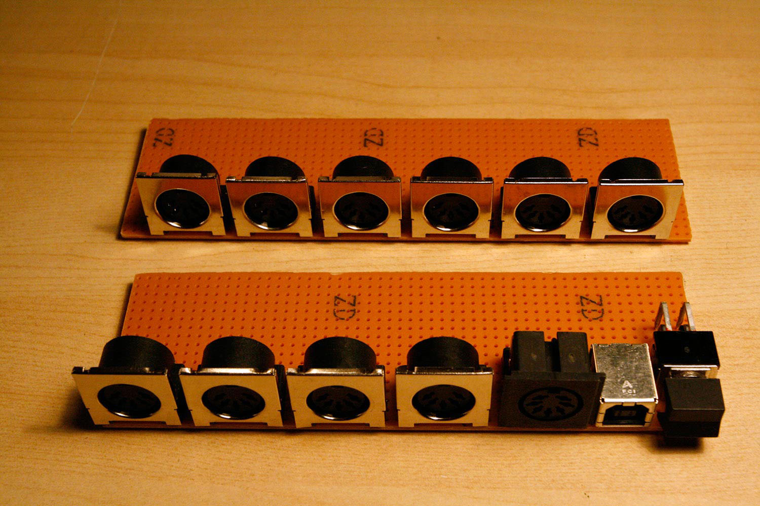
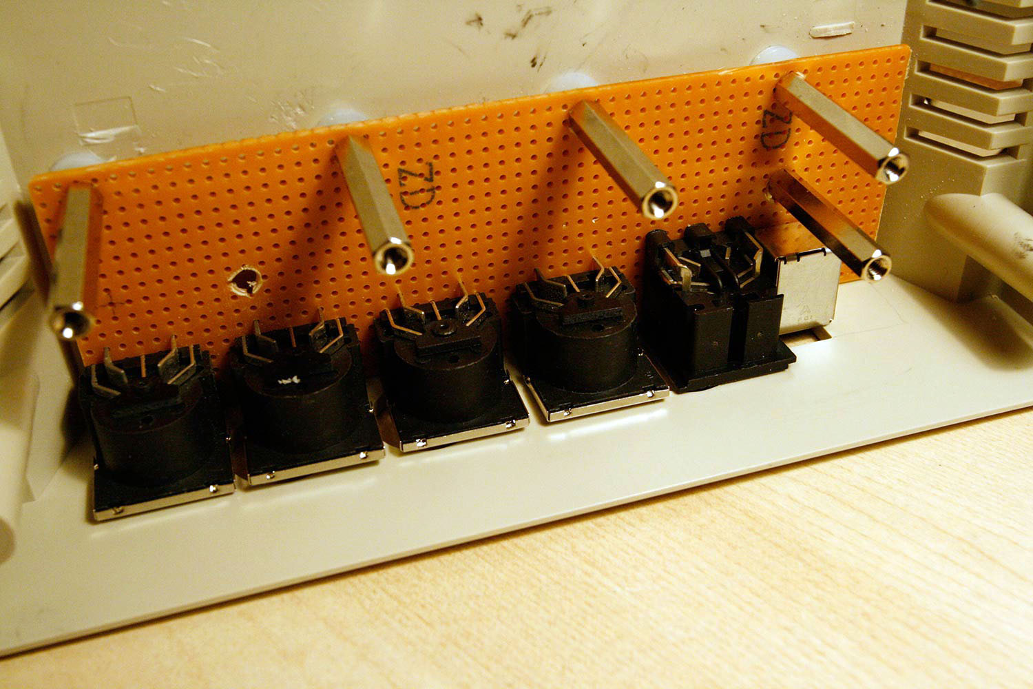
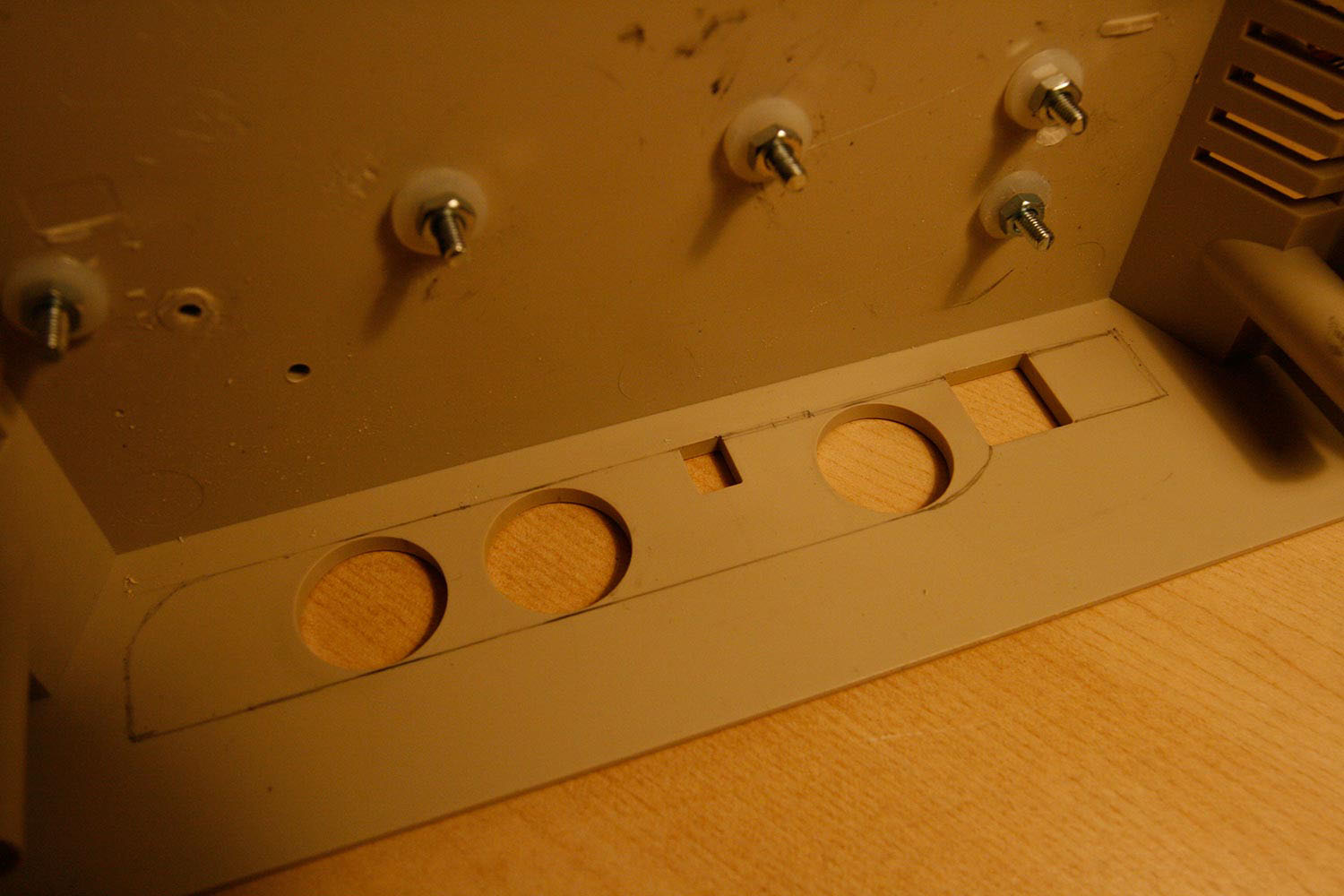
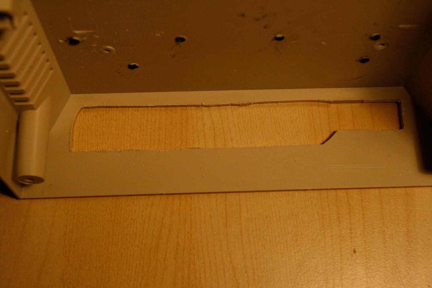
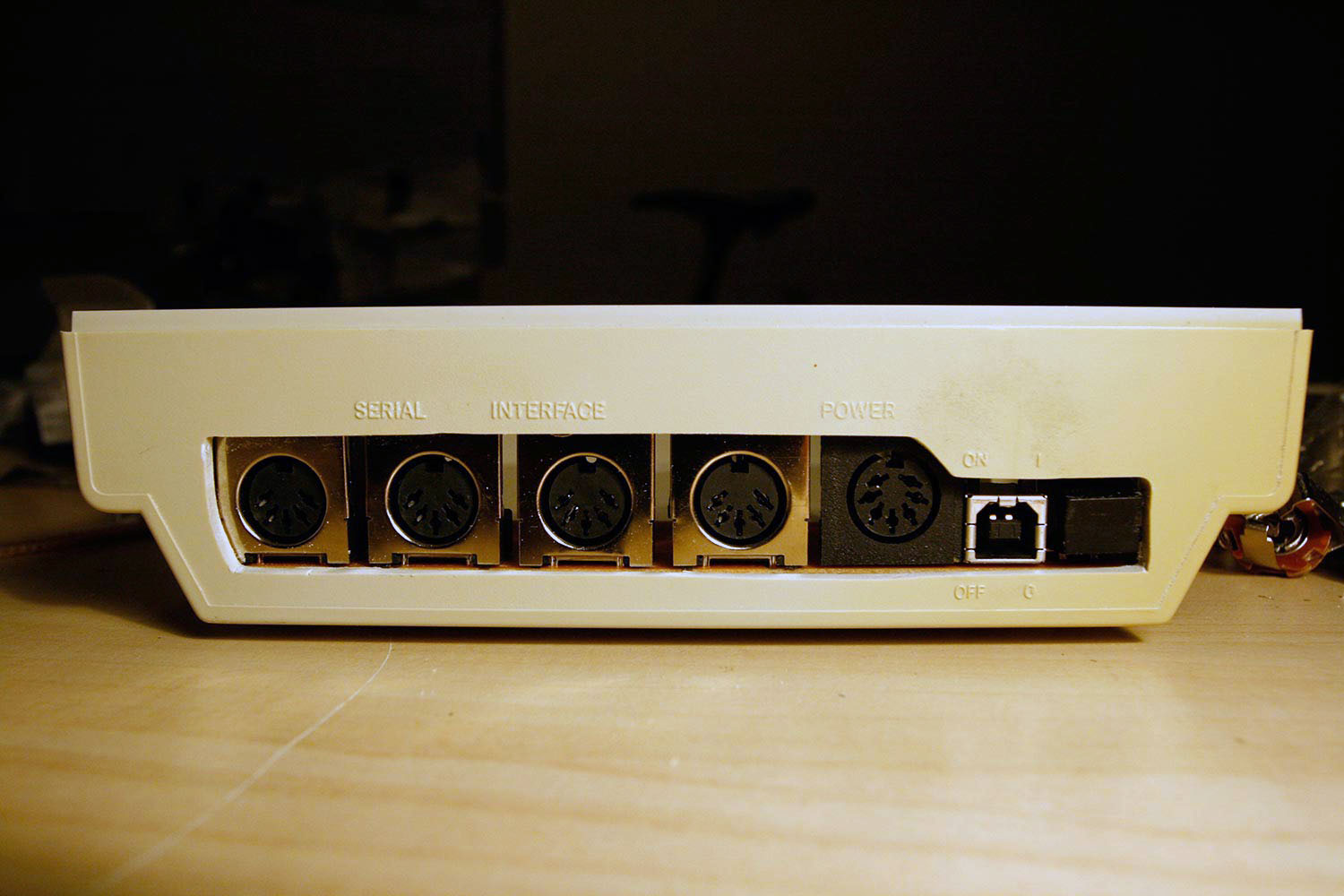
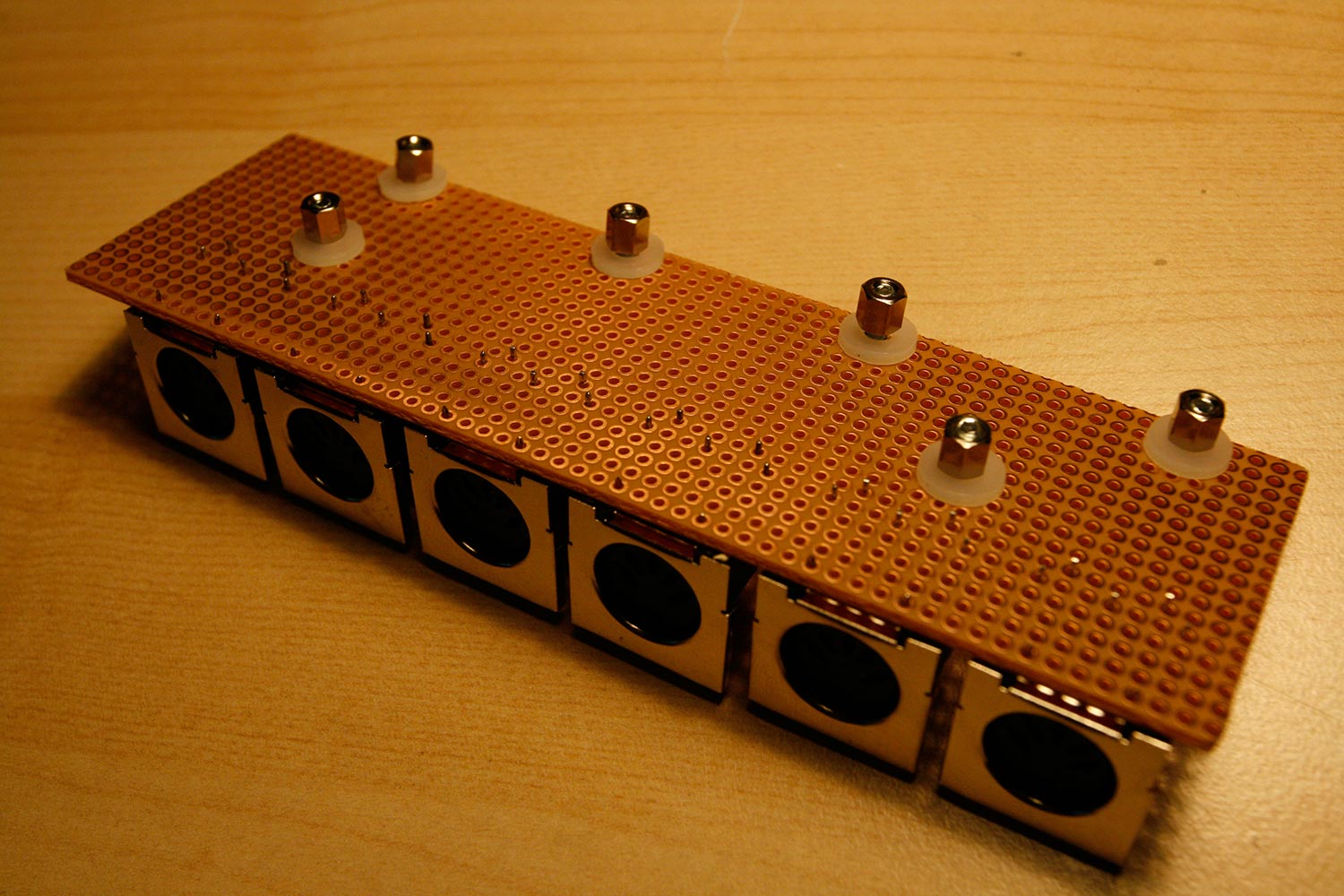
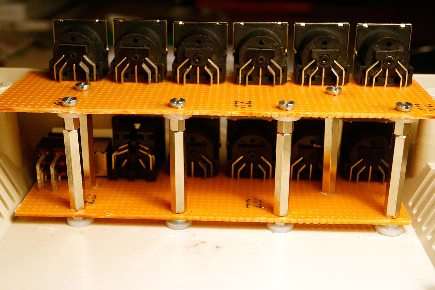
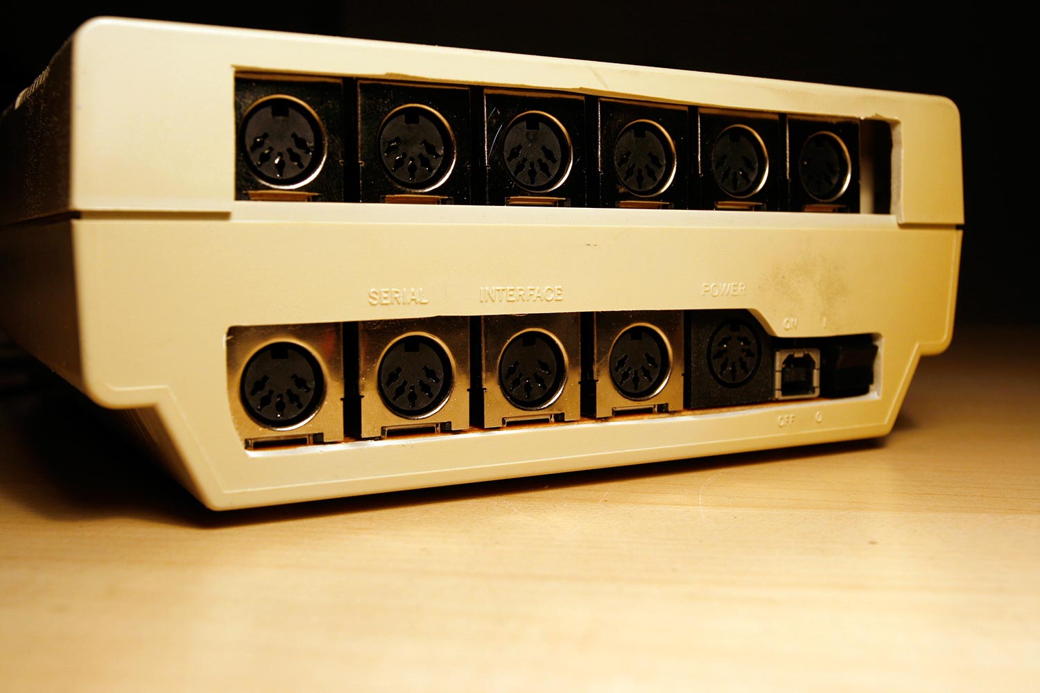
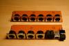
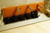
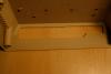
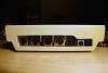
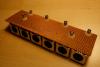
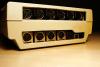
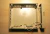
Step 6: Core Case Works: Preparing for the MIDI Socket Backplanes Parts used: 1541-II case (from step 1) 1541 Power Switch (from step 1) 1541 Power Jack (from step 1) 10x15cm Vector board (Any electronics store or Reichelt) 10x PCB-mounted MIDI jack (e.g. AVI Showtech, can use the MIDI jacks that were part of the Core32 module package and the MIDI IIC module packages) 6pcs M3 nylon washer (any mechanical store or Mouser) 6pcs M3 nut (any mechanical store or Reichelt) 6pcs M3x12mm screw (any mechanical store or Reichelt) 6pcs 5mm M3 hex standoff (any electronics store or Reichelt) 6pcs 30mm M3 hex standoff (any electronics store or Reichelt) Bench drill or hand drill with 2mm, 3mm and 4mm drills Dremel tool with cutting wheel (Mechanical) fret saw or hot wire cutting tool Sanding Paper (K180 class) attached to a flat thin surface Mechanical pencil (0.5mm) Description: * Using the dremel with a cutting wheel, create two pieces of vector board with sizes 150x45mm and 138x45mm. Save the 10mm residue. * Test component placement on the vector boards as shown in photo 1. Use a 2mm drill for the stabilizing pins of the usb socket. Remove the power switch again. * Mark a few standoff zones as shown in photo 2 and use a mechanical pencil to draw the drill positions in the case. Drill the case and with a 2mm drill, then with the 3mm drill. Also make sure that the standoff positions do not conflict with the 1541-II rubber feet... I had to relocate the position for the lower left standoff hole. Drill the standoff points on the vector board with a 3mm or 4mm drill. * Test-install the lower backplane by inserting 12mm M3 screws from the bottom, add a plastic washer and a M3 nut to achive the correct height, then add the backplane vector board, and then a 30mm standoff (photo 3). * Draw in saw zones for the fret saw with a pencil by turning the assembly on the side and estimating required space. Remove the backplane again (photo 4) and saw. You can use a fixed guide for the linear saw movements (photo 5), but it will likely not be 100% perfect (photo 6). Use sanding paper on a flat thin surface to correct the worst irregularities (photo 7) * Drill the upper vector board (I used a 3mm drill this time, as the 4mm was a little big) and test-install the upper connector backplane by adding a row of 5mm hex spacers and plastic washers on top of the 30mm spacers, adding the vector board screwed with 12mm screws (photos 8 and 9) * Repeating the above steps, mark the saw zone of the 1541 case top, saw, sand and install (photo 10). Note, that for extra bling, I decided to leave some room on the right side of the upper vector board for a later LAN port extension - therefore the larger cut out. Behold the world´s - first 1541-II with USB connector and 10 MIDI ports. :-).

-
it is really not that difficult or time-consuming to build your own and as your newborn will keep you up all night, you have more than enough time ;-) (self advertisment: you can always follow my on building a custom seq v4 - every step explained, every part listed :))
-
skunks, of course you can, but why would you, cost is neglectable and later on you may need them ;-)
-
hi, the problem would be that you need a usb host (host as in "additional functionality") providing midi conversion. afaik, the core32 offers only a mere usb standard device, so it will be difficult, but i am happy to be told different :)
-
Wilba had prophetic foresight, as usual :)
-
nice soundz, share the patches? btw. have a look @ soundcloud.com, nice interface for music sharing and direct media player integration into this forum :)
-
if you ask me, i would not recommend that from an ergonomics perspective... input accelleration (new FAST2 feature) should be very fine though.
-
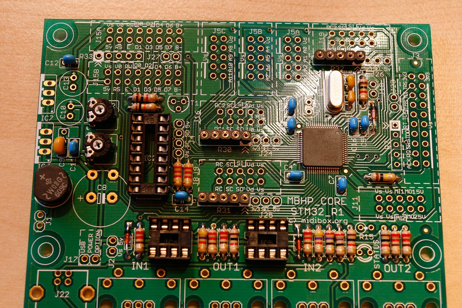
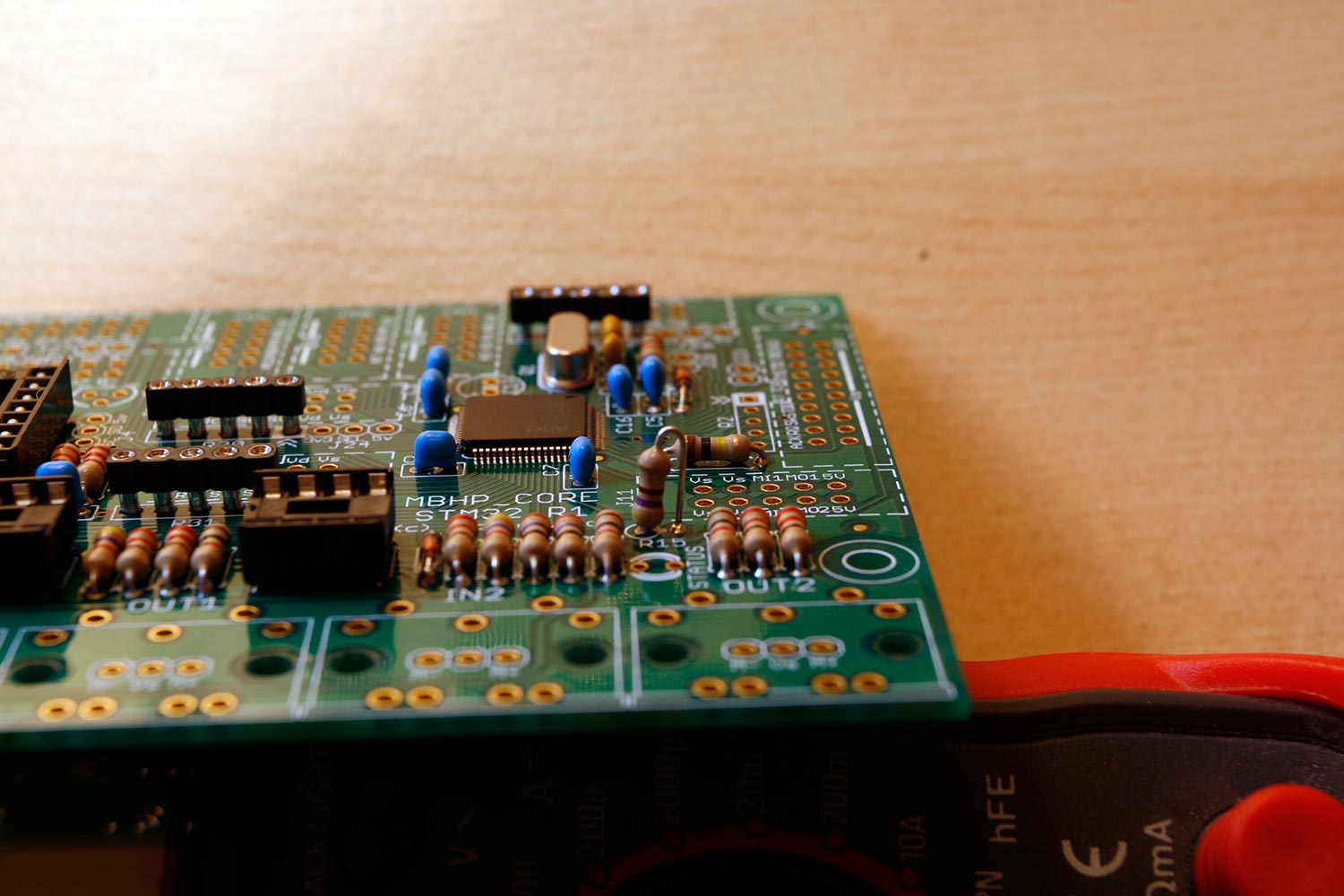
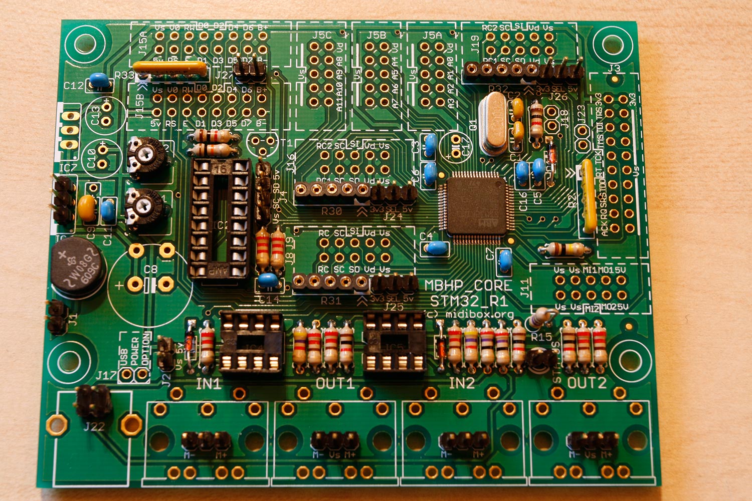
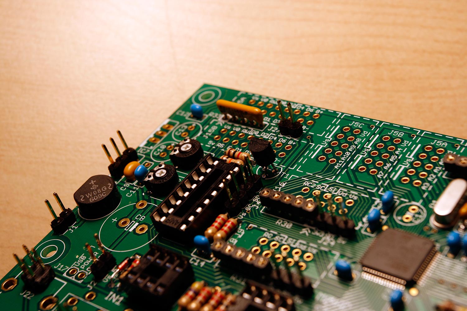
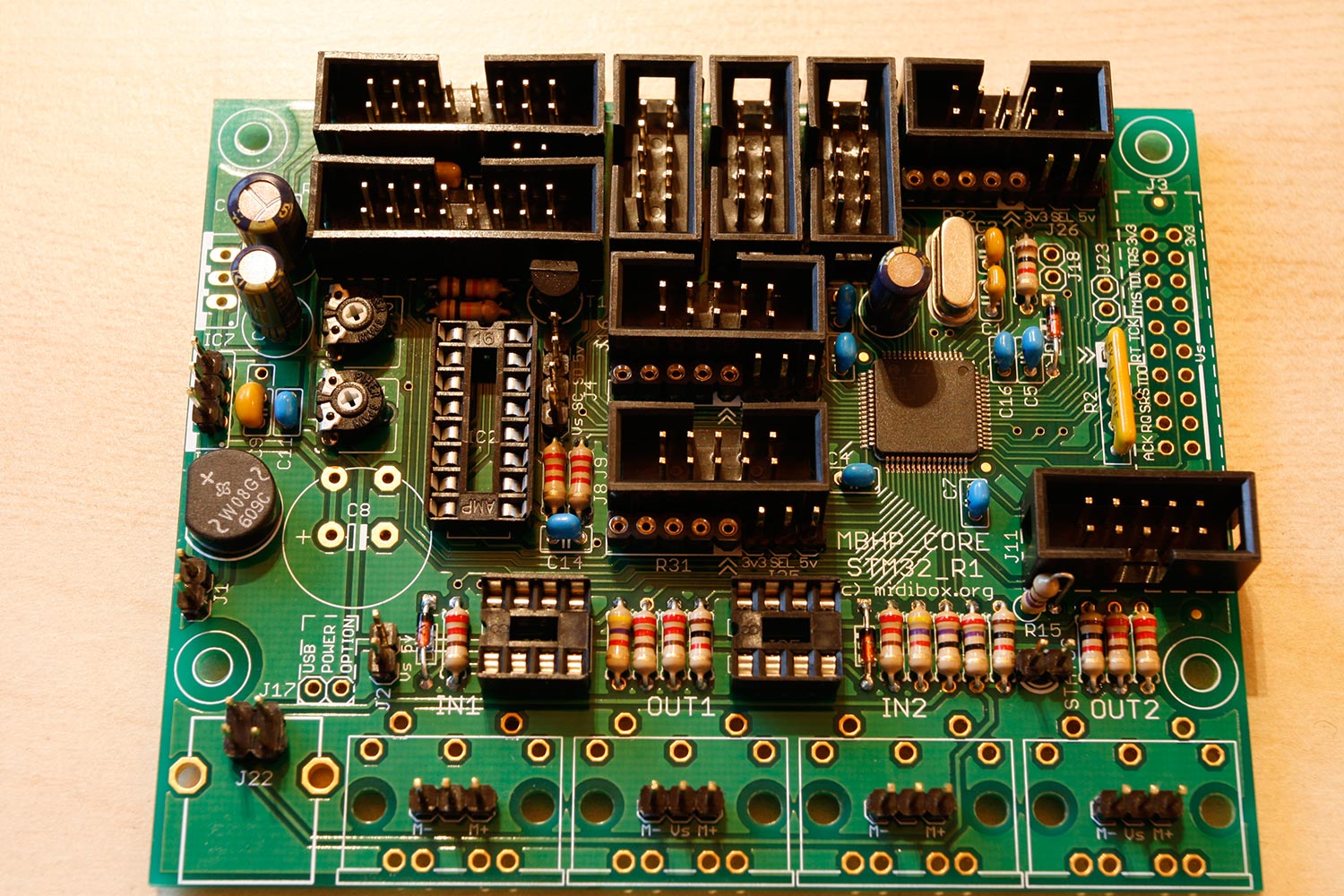
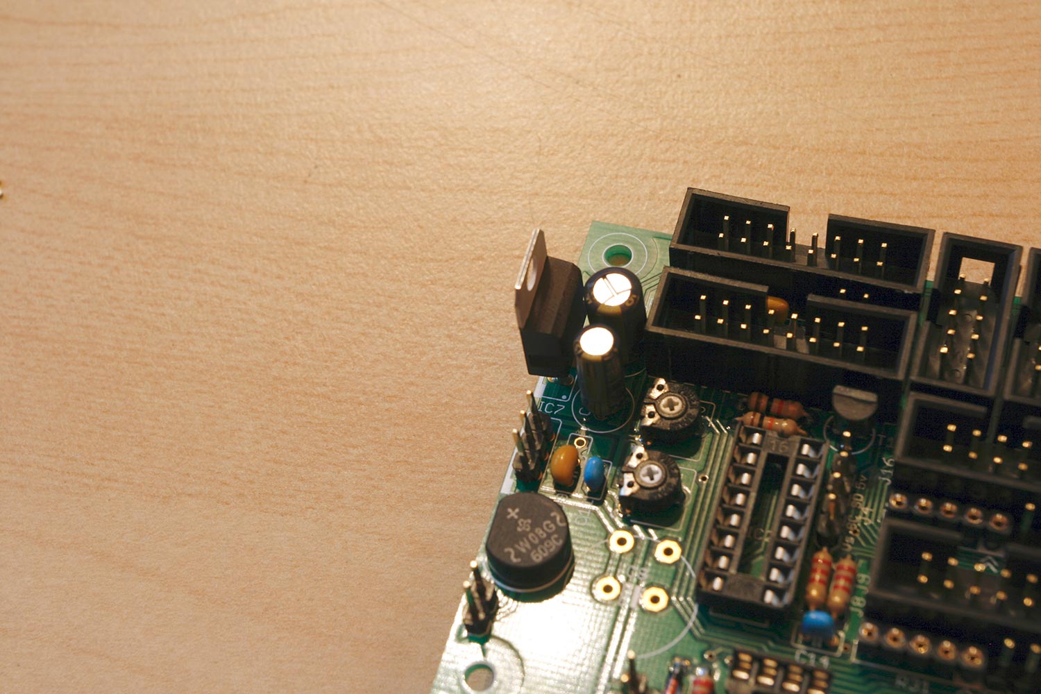
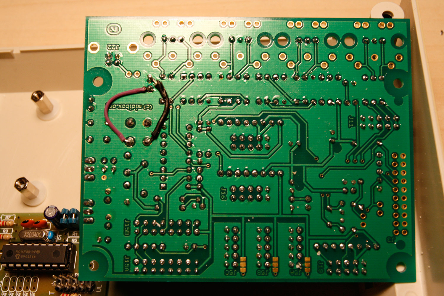
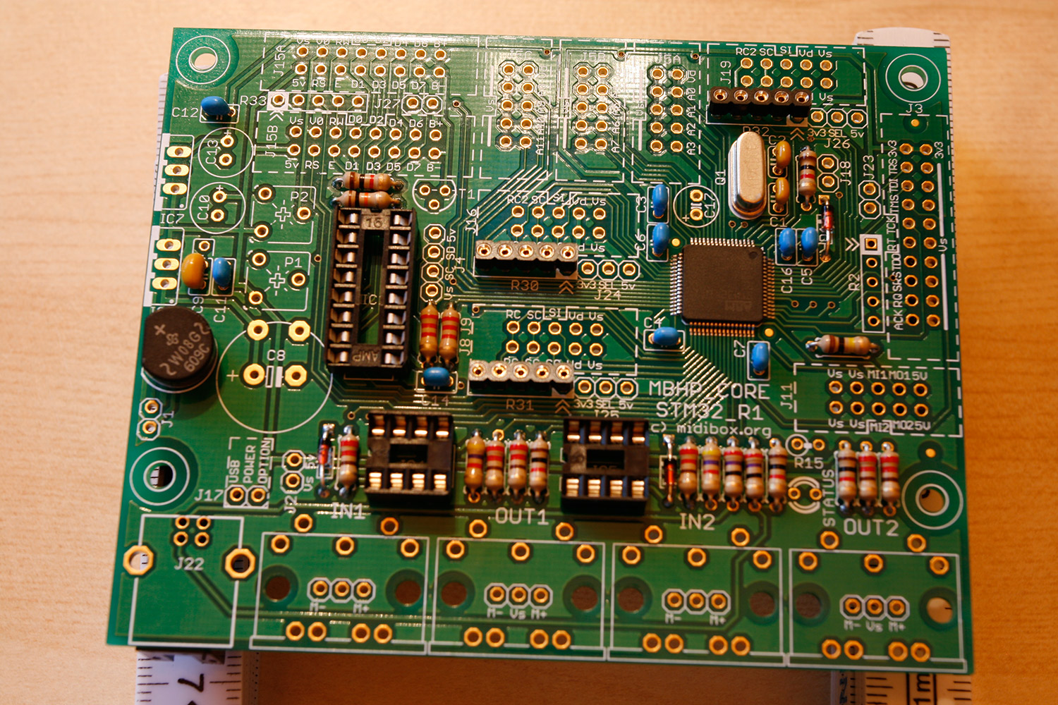
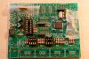
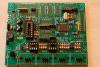
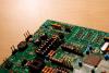
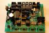
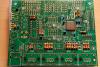
Step 5: Core32 - Adding "the Rest" aka Pots, R15, Resistor Arrays, SIL Headers, T1, DIL Housings, Polarised Capacitors, 3.3V Regulator Parts used: Core32 Module PCB (from step 3) Core32 Parts Kit (from step 3) Additional SIL header (40 pin sil header e.g. from Reichelt) Adhesive Tape (e.g. tesa tape) Description: * Insert the 10 kOhm trim potentiometers into P1 and P2 and solder (photo 1) * Bend the remaining 470 Ohm resistor and insert into R15 as shown in photo 2 and solder. * Insert a 1k Ohm resistor network ("102") into R33 aligning the point to the left (as marked on the PCB), insert the 10k Ohm resistor network ("103") into R2 also aligning the dots. Tack with tape temporarily (photo 3) and solder. If you want to check with your multimeter, measure the "dotted" pin against the other pins. * Insert and solder (can tack them with tape) the external connector SIL headers (you can break the 40-pin connector into smaller pieces by using your fingernail or a knife) as follows: 2-pin into J1 - external power input (we won´t use it) 2x2-pin into J22 - connection to the off-board USB socket 2-pin into J2 - 5V input from SEQ PSU (step 2) - for sanity reasons, I have replaced the standard header later on by a polarized connector - you can do that now :-) 4-pin into J4 - IIC MIDI Module connector 4x3-pin into MIDI IN1, OUT1, IN2, OUT2 - connection to the off-board MIDI sockets 3x3-pin into J24, J25, J26 - voltage selectors for serial ports 2-pin into J27 - if jumpered, the bootloader holds (not executing a crashed app), enabling usb reflashing 3-pin into IC6 - connection to the off-board 7805 voltage regulator 2-pin into STATUS - connection to the off-board power LED * After adding all headers, you can compare your PCB with photo 4. * Bend the legs of the BC337 transistor and add it to T1 so that the flat side of the transistor points to the top of the PCB and solder (photo 5) * Now it is time to populate all DIL connector housings, just populate according to the notch indicators on the board. It is not necessary to populate J3. Turn it over and solder, do it quickly and in "rows". * Populate C10 with the 47µF capacitor aligning the minus pin of the cap to the other pin than the "+" marked pin on the PCB. Likewise, populate C13 with 100µF and C17 with 10µF. Turn over and solder. See photo 6. * Insert the 3.3V regulator LF33CV to IC7, aligning the metal outside to the left and solder (photo 7). * Populate and solder C8 with the 2200µF capacitor aligning the minus pin of the cap to the other pin than the "+" marked pin on the PCB. * Finished soldering, now let´s insert the other parts... * Insert the two 6N138 optocouplers into IC4 and IC5 aligning the marked dots to the left * Insert the 74HC595N into IC2, aligning the notch to the top * Do not fill R30 SIL sockets * Jumper J24 to 3.3V (SD Card) * Fill R31 SIL sockets with the 220Ohm resistor network ("221") aligning the dot to the dot on the PCB * Jumper J25 to 5V (DOUT/DIN modules) * Fill R32 SIL sockets with a 1kOhm resistor network ("102") aligning the dot to the dot on the PCB * Jumper J26 to 5V (AOUT module) * Turn over the PCB and create two connection wires as shown in photo 8. This direct capacitator connection is necessary when more than 100mAs are used by the +5V chain, and 5V are fed directly into J2. * Finished work on the Core32 PCB :-) Smile! Grab a cool drink and compare your result with photo 8. Notes: We will populate the MIDI ports, USB ports, power socket, USB socket and the power LED on separate boards, so we added additional headers. The 5V voltage regulator 7805 is not necessary as we provide the core by +5V power directly We do not need to populate J3 (JTAG wiggler) which provides a means for flashing the STM32, SmashTV has already done this for us :-) We will not add the J17 header, as we always want power from an external power source (not populating this jumper avoids problems when accidentally usb power was selected there and an external power source was connected) Also, J18 is unpopulated, as this would be a connector to the CAN bus, which cannot operate parallel to USB. Finally, J23 is unpopulated, as this one is only necessary for RS232-bootloading, which we are not keen on.

-
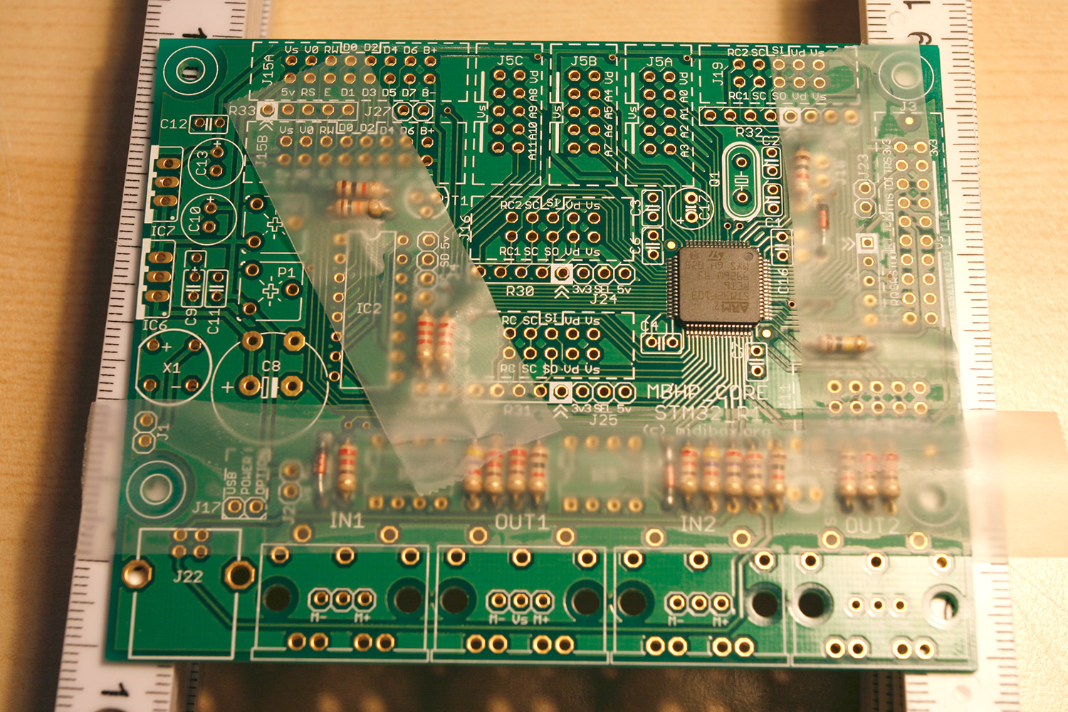
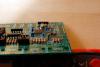
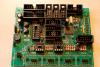
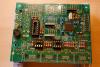
Step 4: Core32 - Solder Ceramic Capacitors, SIL Sockets, Crystal, Bridge Rectifier and IC Sockets Parts used: Core32 Module PCB (from step 3) Core32 Parts Kit (from step 3) Adhesive tape (e.g. tesa tape) Description: * Lift the PCB, so that you can easily drop components. * Drop two 33 pF ceramic capacitors at C1 and C2. * Drop nine 100 nF ceramic capacitors at C3, C4, C5, C6, C7, C11, C12, C14, C16. * Drop a 330 nF ceramic capacitor at C9. * Photo 1 shows the proper locations for these ceramic capacitors. * Drop the 5-pin SIL sockets at R30, R31 and R32. * Drop the 12 MHz crystal at Q1, the bridge rectifier at X1 (align flat side to the left), the 16-pin IC socket at IC2 (align the socket notch to the top) and the 8-pin IC sockets at IC4 and IC5 (aligh notches to the left). * Photo 2 shows the proper locations for the above components. * Tack everything with adhesive tape, turn the PCB over, cut the wires and solder.
-
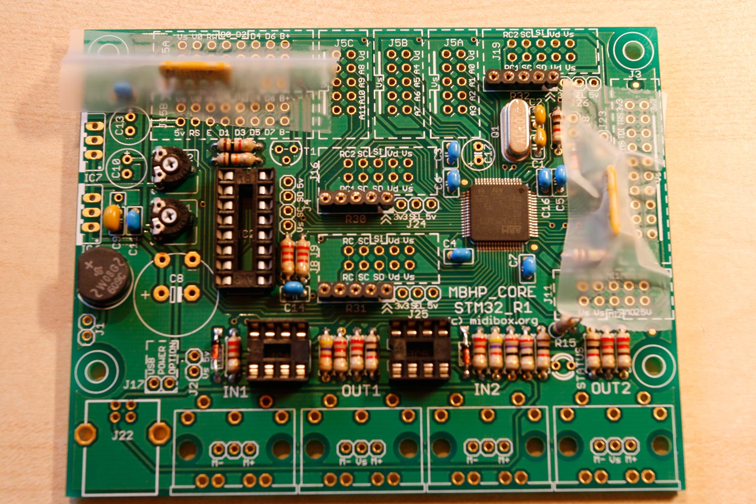
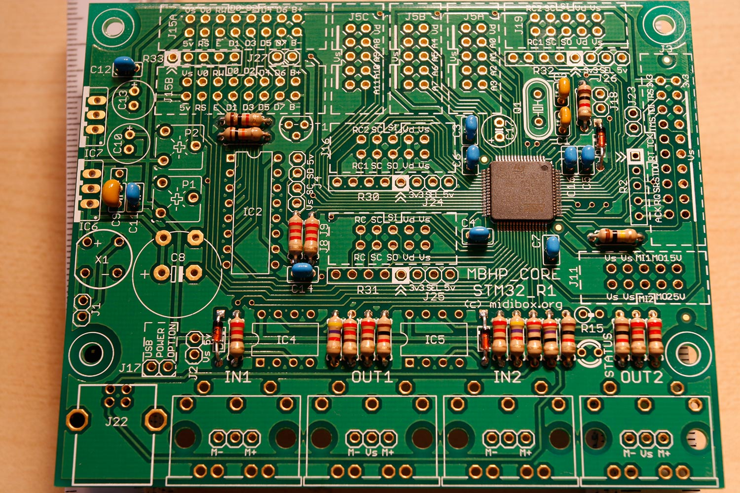
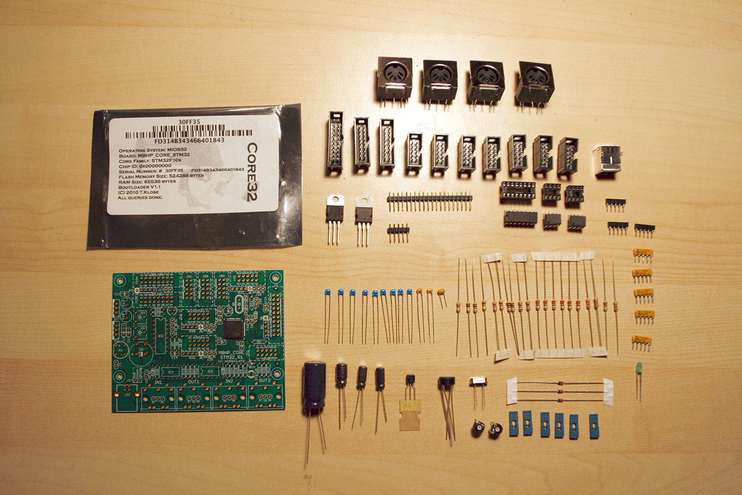
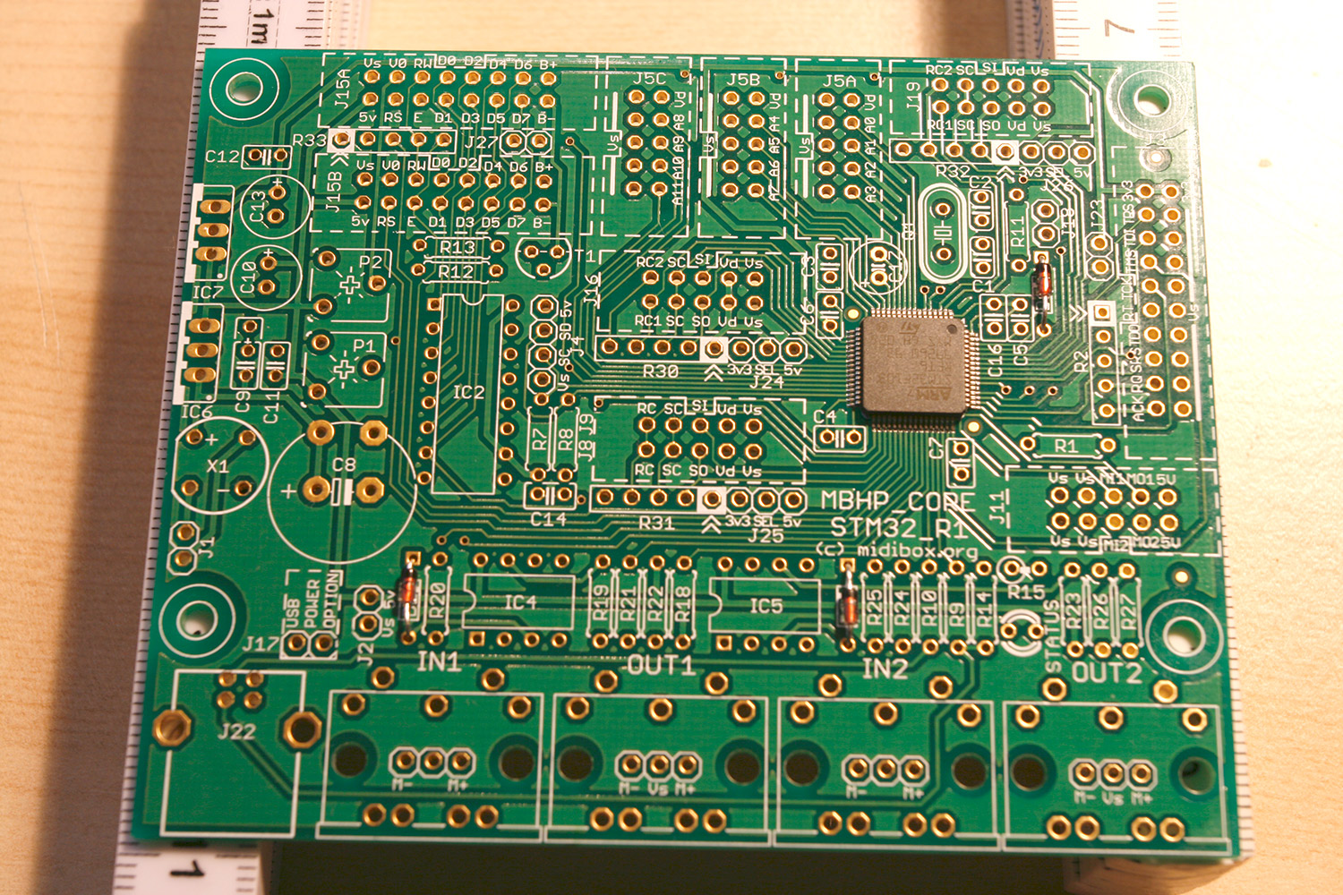
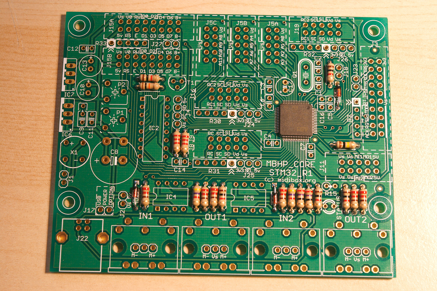
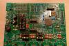
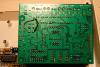
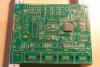
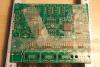
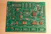
Step 3: Core32 - Solder Diodes and Resistors Parts used: Core32 Module PCB with IC (AVI Showtech - SmashTVs shop) Core32 Parts Kit (AVI Showtech - SmashTVs shop) Adhesive tape (e.g. tesa tape) for "tacking" components Your favourite soldering equipment A multimeter to measure resistor values Description: * Before starting, note that there is another step-by-step tutorial on finishing the Core32 available on ucapps.de and there is a nice interactive PCB map on SmashTVs site here. * Credit, where credit is due. SmashTV does a magnificent job in providing PCBs with the presoldered STM32 core and also delivers a complete parts kit (photo 1). * Following the "solder low components to high components" maxime, we first drop the 1N4148 diodes to D1 to D3 on the lifted PCB, aligning the dot on the diodes to the dot on the PCB (photo 2). Turn over the PCB, cut the wires short and solder. You can "tack" the diodes with a short piece of adhesive tape to make sure they don´t fall out, as they are actually thinner than the already presoldered stm32 chip. * For sanity reasons, use your multimeter to measure the resistor values and drop them into these destination slots: 27 Ohm (red purple black gold) to R9 and R10 220 Ohm (red red brown gold) to R20, R21, R22, R25, R26 and R27 1 kOhm (brown black red gold) to R11, R13, R14, R18 and R23 2.2 kOhm (red red red gold) to R7 and R8 4.7 kOhm (yellow purple red gold) to R19 and R24 10 kOhm (brown black orange gold) to R12 100 kOhm (brown black yellow gold) to R1 Do not drop R15 yet, as this resistor needs to be inserted vertically - we will add this one later as we add higher components. Tack the resistors with tape (photo 3), turn over the pcb, cut the wires and solder. Try to solder quickly (not using more than one to two seconds per solder point) and "in rows" avoiding too much solder. * When finished, your PCB should look like photo 4.

-
yes, i want to try the "soft" buttons for the blm when my seq is complete... at 6 cents per piece it is worth a try (289 pcs) update: i ordered some - those buttons are really nice... could imagine them in a 17x17 matrix smd-soldered to a pcb with smd duo-color leds to achive a tiny and relatively cheap blm.
-
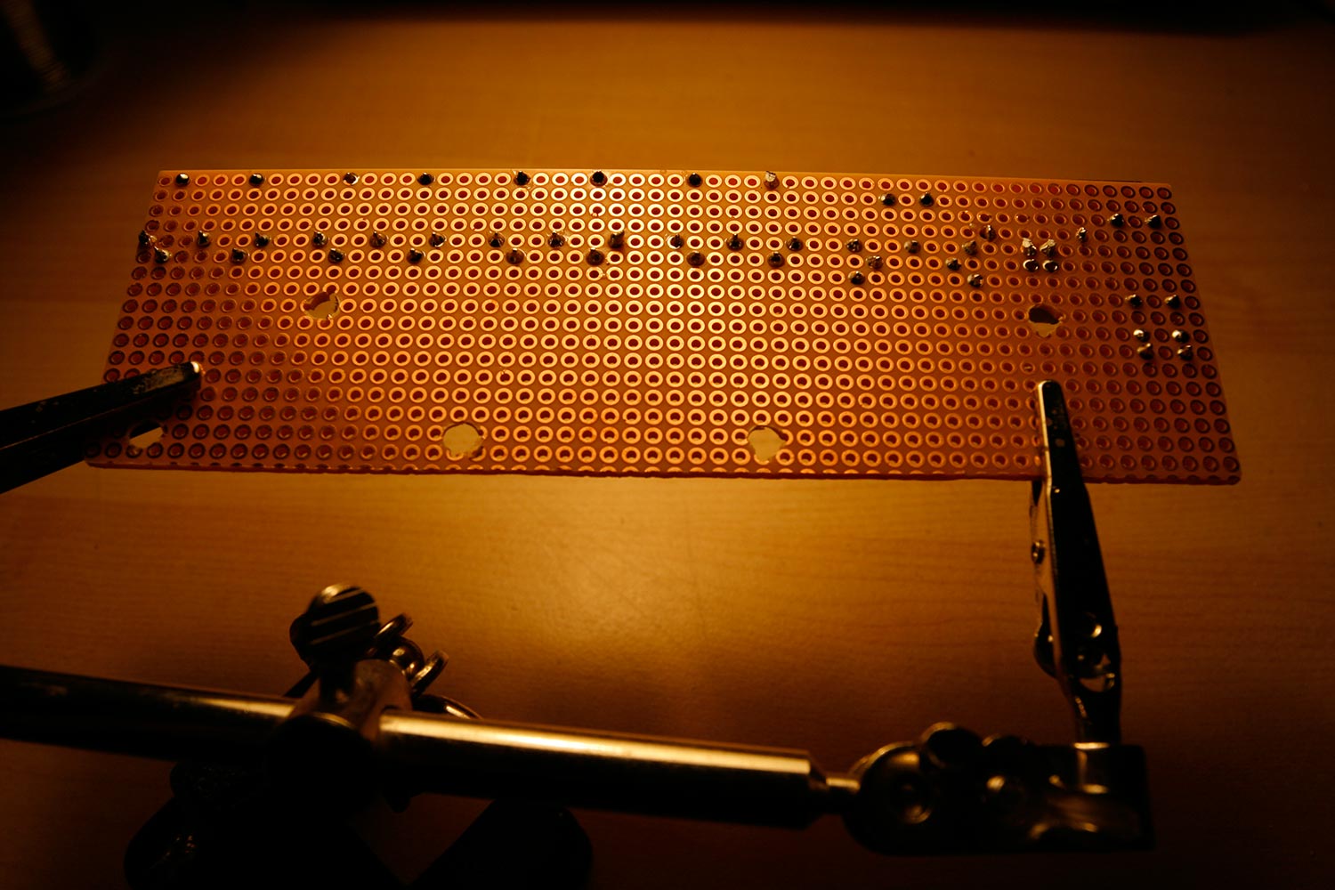
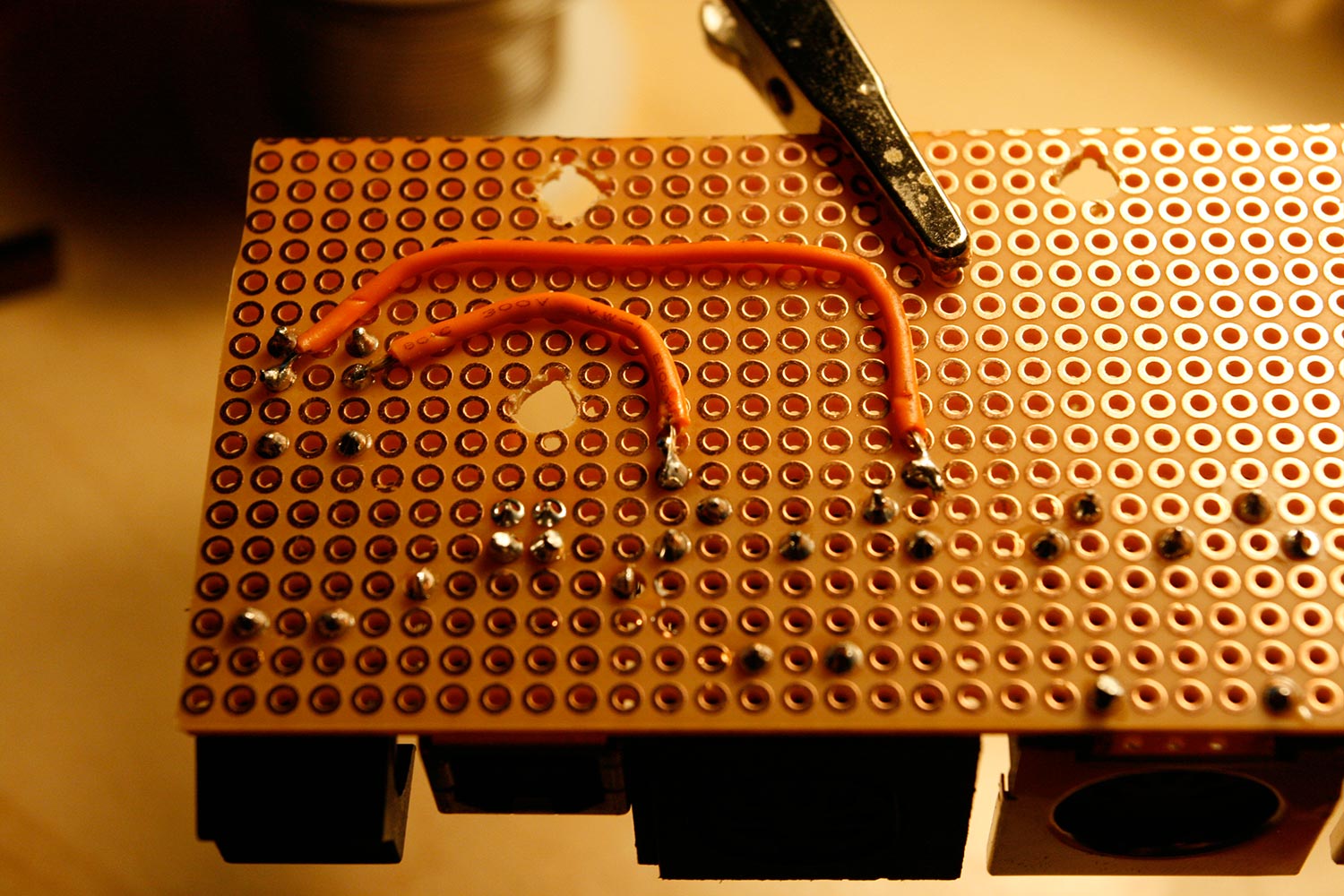
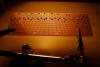
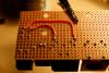
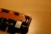
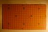
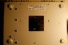
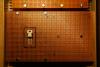
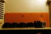
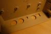
Step 2: Prepare the Power Supply Unit Parts used: * 5V/+12V/-12V open frame PSU (should have 2A on the +5V chain) (Reichelt PSA 25L-301) * PSU plug kit (Reichelt PSA 60-STECKER) * A sufficiently sized plastic or aluminum case (Reichelt TEKO WALL 2 or bigger) * A rubber connector (german: Kaltgerätestecker Reichelt KES 1) * 10 pcs M3 12mm screws (any mechanical store or Reichelt) * 10 pcs M3 nut (any mechanical store or Reichelt) * 4 pcs M3 nylon washer (any mechanical store or Mouser) * Commodore 1541 PCB from step 1 * Commodore 1541 serial/data cable * A bench drill or a hand drill with a 2mm and a 3mm drill * A few centimeters of cable * Electric isolation tape * A 3mm LED and a 220 ohm resistor * A drop of superglue * A dremel tool with a cutting wheel * Your favorite soldering equipment Description: We need proper power for the VFDs, and we also want to use the AOUT_NG module, which needs a bipolar power supply (-12V/0V/-12V), that´s why we use an open frame PSU kit commercially available. * Trim the PSU case, so that the rubber connector and the open frame PSU fit (photo 1). * Cut a piece of the 1541 PCB (photo 2) containing the left serial port connector, so that it fits neatly into the case (photo 3). Don´t forget to cut the surface connections with your dremel tool (photo 4). * Solder six power connection wires to the backside of the piece of the 1541 PCB (photo 5). Don´t mind the alignment, we will measure the voltages later on. * Drill the piece of the 1541 PCB and the bottom of the case. Fasten the serial port connector PCB with M3 screws and nuts (photo 6). Mark the area, where we will plug the serial cable (used as power cable) and cut it, so that you can plug in the cable. * Install the open frame PSU using the same method (drill the floor of the case and insert M3 screws, use nylon washers as spacers and fasten with M3 nuts (photo 7). * Crimp and solder the AC mains connector cable and connect to the PSU. Fasten the rubber connector using M3 screws and nuts (photo 8). * Create the power connector by crimping the six power connection cables. Add a small cable for the power LED to a +5V and a GND line (note: if you measure using your multimeter with power on, take security precautions, as there is dangerous voltage nearby). * Solder a 220 ohms resistor and a 3mm LED to the end of the cable and isolate with electric tape (photo 9). * You should drill the case for better air ventilation. You can use graph paper and a 2mm and a 3mm drill (photo 10) to create a matrix of holes. Also create a 3mm hole for the power LED. * Fasten the LED using a drop of superglue. * Enjoy your new PSU, it should look like photo 11. All voltages should be available on the serial connector cable, which we will use to power the Core32.


-
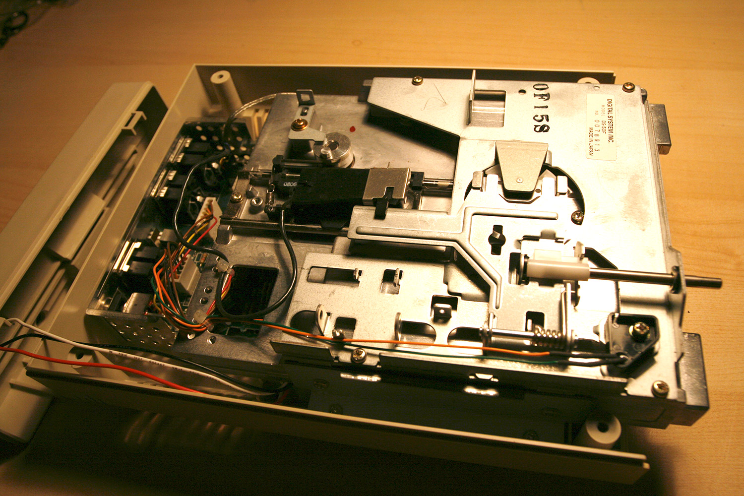
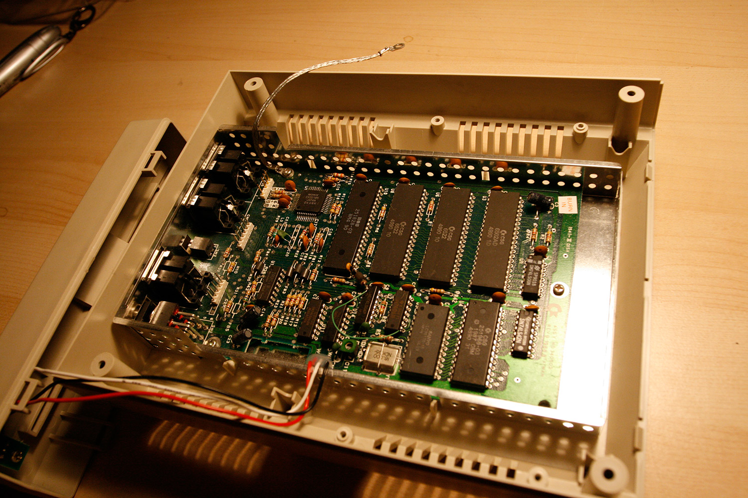
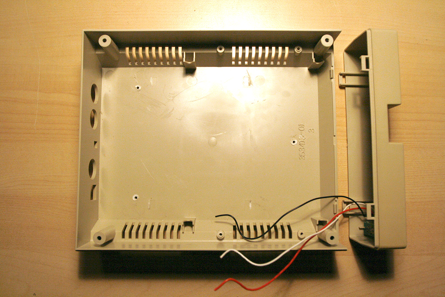
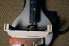
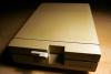
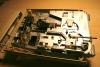
Step 1: Prepare the Case for the Sequencer Core and Modules Parts used: Commodore 1541-II floppy drive (available from ebay) Phillips screwdriver Cutter knife Your favorite desoldering equipment Description: * Every good journey should begin with massacre :-). Grab a malfunctioning 1541 disk drive in good physical shape (photo 1). * Disassemble (photos 2 to 4) * Use the cutter knife to cut away any inner plastic spacers used to hold the 1541 mainboard (photo 4). * Grab the 1541 PCB and desolder the right serial port and the power switch. * Do not throw away the 1541 PCB yet, we will need it it the next step. * Have a cool beverage and enjoy the carnage :-).
-
Hola, after getting infected with the MB spirit, it is time for another realtime photo-documented feed of a new project, this time a custom MIDIbox SEQ V4 :-). The last photo tutorial (MB-6582 Control Surface with partslist is available (and still waits for a move to the SID section by nILS :-))). This MB SEQ variant will include a lot of custom tinkering and therefore has much more room for mistakes and utter failure. If this happens, I expect compassion and tears from you, fellow MBers ^^. What to expect? We will build a MB SEQ Core in-a-box (retrofitted to a Commodore 1541-II case), a breakout-box Control Surface in a slim, thin and wide aluminium box which can be mounted directly below your master keyboard to minimize hand movements when switching between sequencer and keyboard action. Aiming for VFDs, an integrated AOUT-NG module for Control-Voltage output, duo-color flat-head rectangular step LEDs, a drilled LED matrix bpm indicator, nice Wilba-CS-style keycaps and switches, push-accelerated step encoders and an external BLM. Every step will be photo-documented. I will provide a full parts list and links to parts sellers, where possible. People interested in building a SEQ from this tutorial may need to adapt a few things... they may not want to use the VFDs or the commodore floppy case for the base unit, but these parts can be substituted. For anyone interested in building a SEQV4 more quickly, I would totally recommend using Wilbas PCB - it is straightforward and saves time and money. In other words: only use this approach if you have space constraints and like the idea of a slim breakout-box CS or wish for a personal customized control surface layout. Thanks to everyone who made this possible, of course especially TK. and Wilba, who have done a terrific job in realizing wishes, adding requested features to the MBSeq-Software within a week, sending out tech documentation within less than an hour and answering dumb questions... the support here is more awesome than Chuck Norris doing push-ups :-). Also thanks to SmashTV for providing parts in fantastic quality and Seppoman for the AOUT_NG module. Ah, and not to forget nILS ... :-). As usual, I am interested in your comments on the way - note though, that they might get deleted afterwards, if this project turns out to be working in the end :-). Lets go and have fun! Hawkeye
-
nice find, the prices are very good!
-
thanks, seppoman, will keep you posted. as a sidenode, it is incredible how nice they look, in my opinion, they offer a lot more visual eyecandy than common lcds...
-
I googled and identified the lower right one as the AS-4oh4 prototype version with zero polyphony ambience. and i said hit the head, not the foot :)
-
my brain processed that matter in a low priority background task for the last days... and my first outrage has been quite shifted... the point is, that we will never be able to control what is being sold on a private basis between the people out there... we may be angry and blame profitmakers, but it will be incredibly hard to stop them. and legal effort is never nice effort. heck... I guess it would even be quite difficult to shut down a chinese (no offense intended) manufacturer cloning TKs and Wilbas code and designs...
-
Ok, i really do not want to be in conflict with you guys, you have given me too much ;-). Just removed the youtube comment... but in my opinion this deal is bad and we need :super: to clean the world from evil :)
-
Wilba, wtf, why do you protect this guy - he charges more than double than its worth - in my eyes that is commercial intent, TK. wrote in the rules that he will deny overpriced sale requests and if this not overpriced, i don´t know what...