Hawkeye
-
Posts
3,636 -
Joined
-
Last visited
-
Days Won
36
Content Type
Profiles
Forums
Blogs
Gallery
Everything posted by Hawkeye
-
so it runs on caffeine? likeable! :thumbsup:
-
 stylish lighting ;-) congrats!
 -
yes, if the gods allow it, it will be a seq v4 eventually ;-). that is, if the cables to the control surface are not too long... TK. said it might be the case... if that happens... yes... we will see ;-)
-
joa, hat richtig Spaß gemacht - danke dem Gastgeber :), vielleicht lädt Phunk ja mal ein paar Bilder hier hoch...
-
Also, try to avoid using a gcc 4.4 based cross-compiler, which comes with the current CodeSourcery distribution. I had trouble with it (guess it has something to do with optimization or so). Bye, Peter
-
 nice! :)
 -
+1 for an improved midibox psu - in my eyes it makes not too much sense to have n PSUs for n midiboxes... would also recommend to consider adding a bipolar output section with +12/0/-12V for aout... we could reuse the standard c64 power plugs "emulating" a standard c64 psu, making it compatible with existing hardware like the manyfold MB6582s. Also the C64-II plugs have a few spare pins left, which might be used for bipolar voltages.
-
thx & yes i like it now! ;-) have fun building your cs!
-
Sorry, i have no user experience with the SEQ yet, too, just building one... but looking forward to using one for the first time on sunday :-) Below every rotary encoder there should be a button, called "general purpose button" in the handbook. Such a button in conjunction with the rotary encoder allows to modify things displayed on the screen directly above it. That´s why they need to be aligned below each other... and aligned to 5 character cells (1/8th of 40 characters) on the screen.
-
I like the "menu buttons" below the menu jog wheel. Like this, it may be possible to navigate the menu with one hand only this way... But what about the step buttons - should not they be aligned to the step rotary encoders? Thanks for the button link!
-
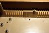
Step 14: Building four IIC MIDI OUT Modules Parts used: * 4pcs MIDI IIC PCB (AVI Showtech) * 4pcs MIDI-preflashed PIC16F88 (AVI Showtech) * 16pcs 220 ohm resistor (any electronics store or Reichelt) * 4pcs 20MHz crystal (any electronics store or Reichelt) * 8pcs ceramic capacitor 15pF (any electronics store or Reichelt) * 4pcs ceramic capacitor 100nF (any electronics store or Reichelt) * 4pcs 18-pin IC sockets for PICs (any electronics store or Reichelt) * 4 x 14 pins of DIL header (any electronics store or AVI Showtech) * 4 x 7 pins of SIL header (any electronics store or AVI Showtech) * 4pcs SIL-header jumpers (any electronics store or AVI Showtech) * 4pcs electrolytic capacitor 10 uF 35v (any electronics store or Reichelt) * 8pcs M3 10mm hex standoff (from step 6) * 8pcs M3 5mm hex standoff (from step 6) * 8pcs M3 12mm screw (from step 6) Description: * For efficiency reasons, you can work on all four PCBs at once, just repeat the below steps for every board: * First drop the 220 ohm resistors (red, red, brown, gold) into R1, R2, R9 and R10 (photo 1), turn over the PCBs and solder. * Continue with the crystal, which should be placed at Q1 (photo 2). * Now drop and the solder two 15pF ceramic capacitors to C1 and C2 and one 100nF ceramic capacitor to C4 (photo 3). * Add the IC socket and solder it (photo 4) * Now drop and solder a 10-pin DIL header to J2, a 4-pin DIL header to J3, two 2-pin SIL headers to the left and right LED slot, and a 3-pin SIL header to the MIDI out port (photo 4). * Finally, add the 10 uF electrolytic capacitor observing polarity (connect the "- pin" opposite to the "+" symbol on the PCB). * Insert the PIC, aligning its notch with the notch on the PCB. Photo 5 shows a completed MIDI-out module. * Now, jumper J3 to four different values for the four PCBs (photo 6 - from left to right the modules will be MIDI OUT4, 5, 6 and 7). * Install the MIDI out modules in order MIDI OUT 4 on the lower right, MIDI OUT 5 on the lower left, MIDI OUT 6 on the upper left and MIDI OUT 7 on the upper right. Photo 7 shows the assembly stage (three modules installed). Use 10 mm hex standoffs on the lower PCBs and fasten the upper PCBs with 12mm screws and additional 5mm hex standoffs from the top (you can also use single 15mm hex standoffs, of course). Addendum: I forgot to solder in resistors R4/R5 (10k each) and learned the hard way, that proper IIC address selection is not possible without them :-). I´d recommend you install them, if you want to use more than one IIC module in your SEQ :-)


-
I like it, especially the Machinedrum-like buttons - do you have a supplier for them? When designing a UI, it is most important to separate different "logical regions" into different comprehendable blocks. The human eye has problems when it is confronted with a large mass of same-sized objects (buttons in a grid). Colors may help, lines around sections may help, placing button groups apart from other button groups may help... but it is a difficult task... especially if space is limited and you want all buttons. In the end, you must decide if you like the button positions, and how your workflow is. I decided to build a very slim CS to be attached below my master keyboard to minimize hand movements between recording and playing... it is not done yet... a difficult task to decide what to put where :)
-
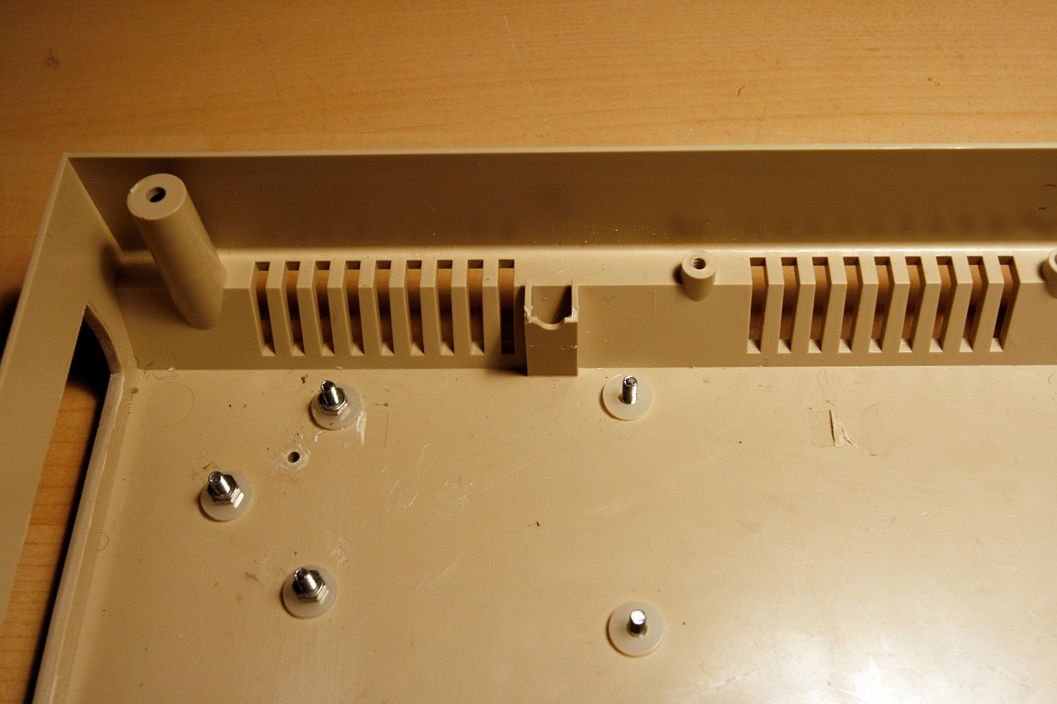
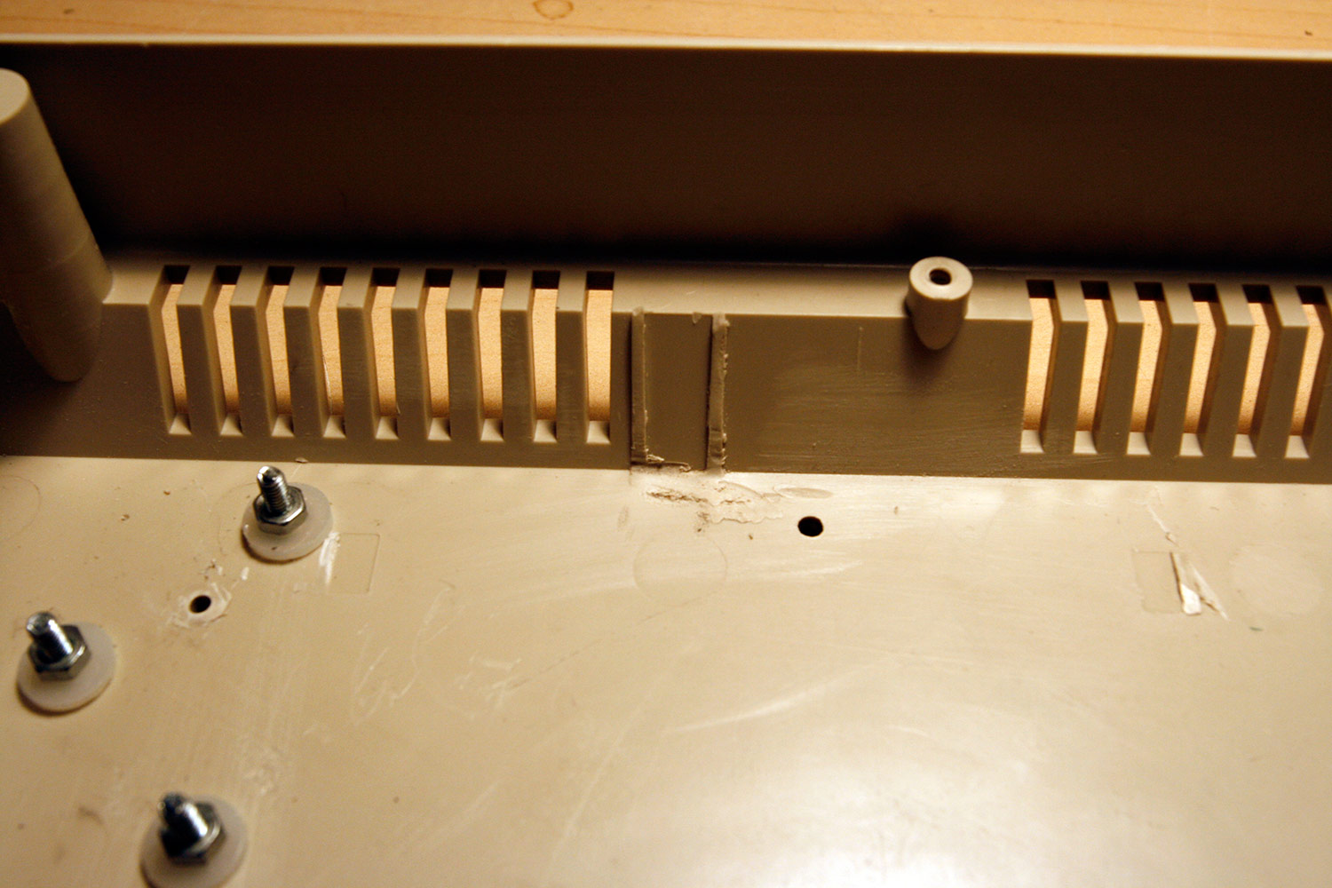
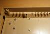
Step 13: Preparing the Case for the IIC MIDI Modules and the DIN/DOUT Sandwich Parts used: * A dremel tool with a cutting wheel * A bench drill or a hand drill with 2mm and 3mm drills * 2pcs MIDI IIC module PCBs (to find standoff drill positions) (AVI Showtech) * DIN or DOUT PCB (to find standoff drill positions) (AVI Showtech) * 12 pcs M3x12mm screws (from step 6) * 12 pcs M3 plastic washers (from step 6) Description: * First, remove all components from the case and using your dremel tool, cut away the plastic edge (photo 1), which is in the way of the MIDI modules (photo 2). * Reassamble and lay two IIC MIDI PCBs and a DIN or DOUT PCB out as shown in photo 3. Use a pencil to mark the center of the PCB holes to mark the new drill hole positions. * Using a 2mm drill first and a 3mm drill afterwards, create the 12 additional standoff drill holes. * Insert M3x12mm screws and place plastic washers on top (photo 4). The case is now ready for the installation of these modules.
-
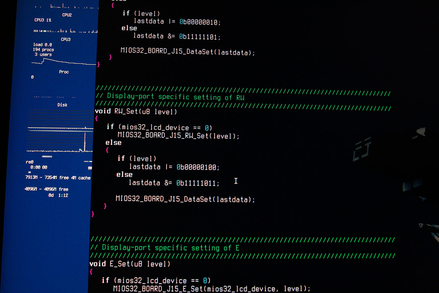
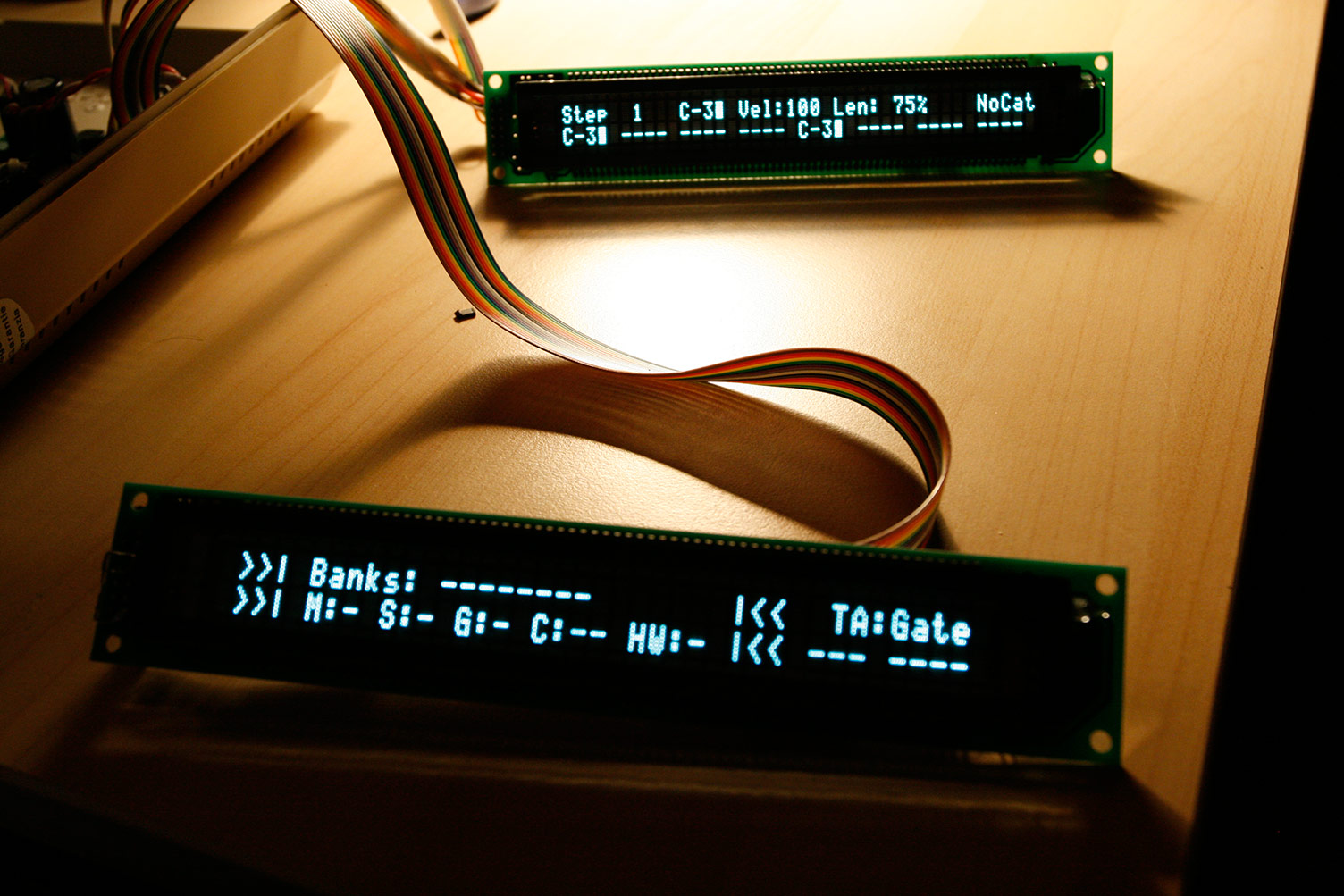
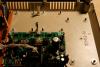
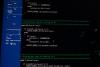
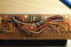
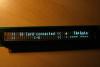
Step 12 (optional): Coding Intermezzo (or: two screens working, hooray!) Parts required: Your favorite gcc compiler Calmness, tao and a supportive partner Description: Last week I managed to get one "cheap" Futaba VFD up and running thinking all my problems would be solved, by switching the normal 8-bit character lcd driver into 4-bit mode (as the display contained replaced characters in 8-bit motorola mode). Pah, when test-attaching the second display and thinking it would be as easy as that, both displays stayed dark. Thinking of a power (surge) problem at first, I reworked the power supply of the Core32 (I have documented this now in step 2...), supplying up to 2A of 5V direct to the Core32 - and of course that did not help, both displays still stayed dark. Suspecting that "cheap" really meant "cheap in a compatibility-with-established-standards-way", I tested everything including switching back to 8-bit mode (garbage output), mixing the VFD with a classic LED backlit LCD - this worked, depending on which port the classic LCD was connected to... I was near to pulling my hair, not at all understanding what the problem was. At some time I had the idea, that those displays might not be able to share the same control lines (RS, RW - E1 is already separated from E2), i therefore moved these lines to the by then "unoccupied" DB0-DB3 data lines (the 4-bit necessity proved to be the way out of this mess by giving us a few free data lines). My 9-wire-per-vfd cabling looks like this: * J15A DISPLAY 1 WHAT * 1 -> 1 GND * 2 -> 2 VCC 5V * 4 -> 4 RS * 5 -> 5 RW * 6 -> 6 E * 11 -> 11 DB4 * 12 -> 12 DB5 * 13 -> 13 DB6 * 14 -> 14 DB7 * ------------------------- * J15B DISPLAY 2 WHAT * 1 -> 1 GND * 2 -> 2 VCC 5V * 8 -> 4 DB1 -> RS * 9 -> 5 DB2 -> RW * 10 -> 6 DB3 -> E * 11 -> 11 DB4 * 12 -> 12 DB5 * 13 -> 13 DB6 * 14 -> 14 DB7 Also I had to change much of the app_lcd driver to "emulate" the control lines for the second display on the unused data lines 0-3 (photo 1)... What should I say... it worked in the end (photo 2), it just had to... but I guess I spent more than 20 hours on the problem. Would have been cheaper to buy more expensive Noritake VFDs :). I´ve attached a changed app_lcd.c for the at least incompatible but probably quickly hacked holtek 16514 vfd display driver chip. If permitted by TK after a code review, I would add this to the source repository for those poor people like me, who own that chip ;-). I´ve also reattached a now twin-futaba-vfd-capable version of mbseqv4 beta 31 for your convenience. app_lcd.c project.hex
-
sorry, did not understand "the card is securely" leds will be most likely special-format dual color leds from digi-key or reichelt, but choose anyone you like rotary encoders (not potentiometers) are alps stec encoders from reichelt For a detailed list of proven-to-be-working control surface parts, have a look at Wilbas page regarding his control surface: http://www.midibox.o...seq_parts_guide Also read the hardware options section of the mbseq manual on ucapps.de to understand which modules you need and how they are interconnected: http://ucapps.de/mid..._manual_hw.html Good luck!
-
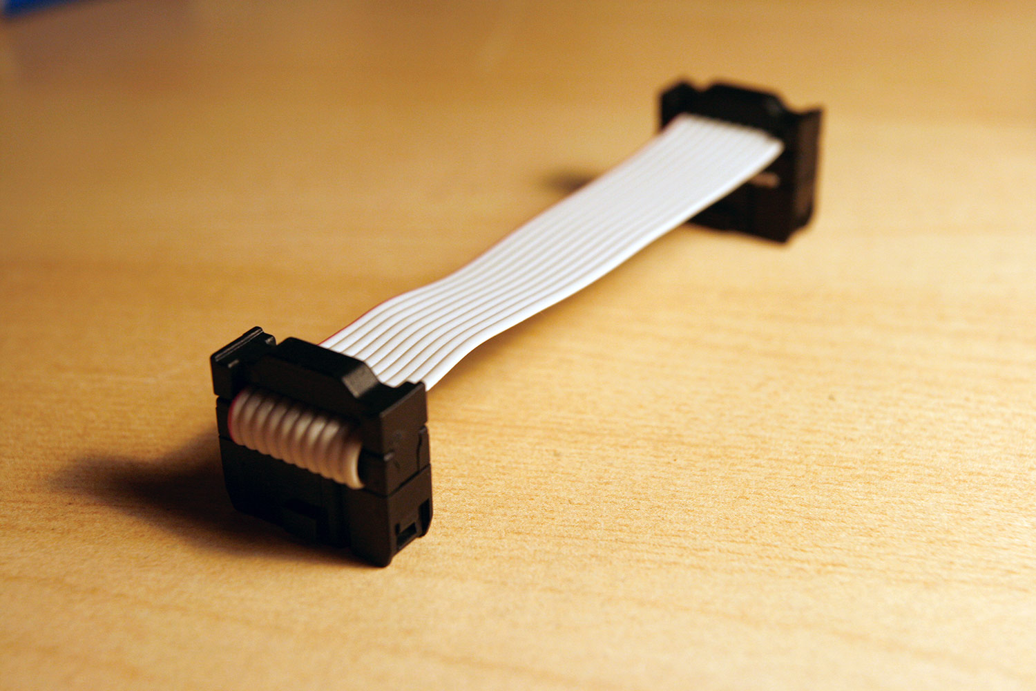
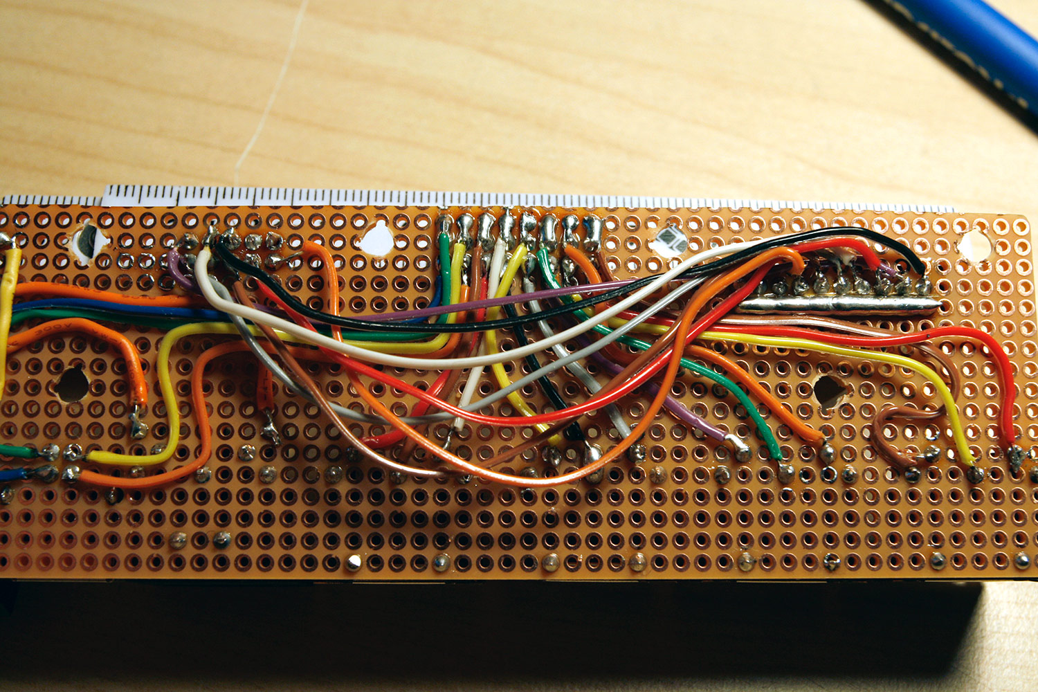
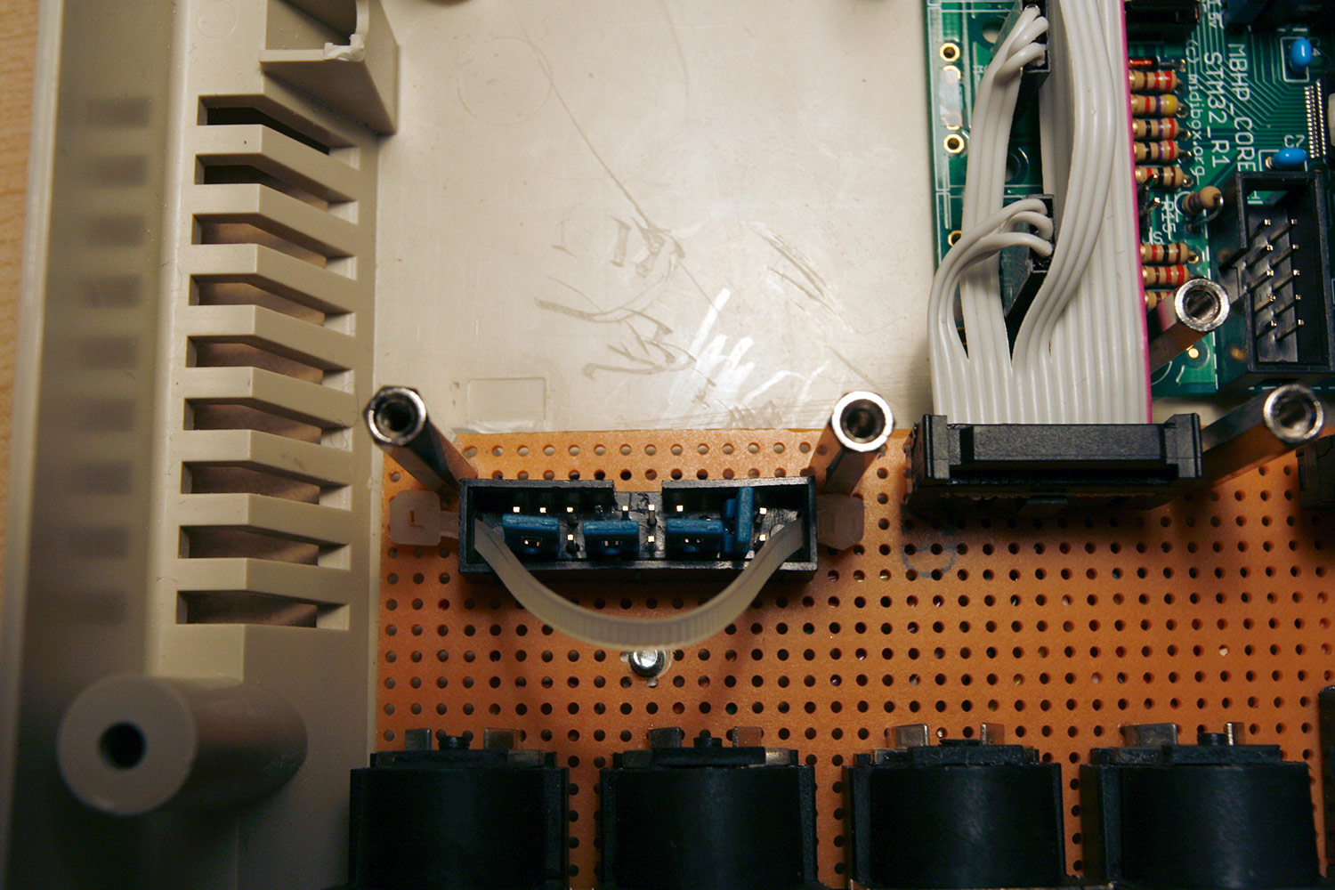
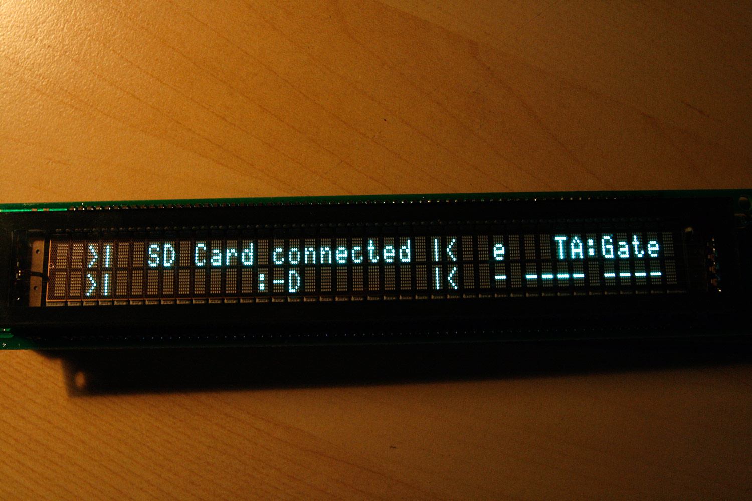
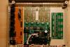
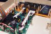
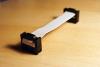
Step 11: Attaching a SD Card Parts used: * SD card of your choice (SDHC worked in my tests), does not need to have much capacity, but choose a trusted brand * 10-pin ribbon wire (e.g. from AVI Showtech, but every electronics shop should carry this) * 2pcs 10-pin IDC connector (e.g. from AVI Showtech, but every electronics shop should carry this) * 10-pin DIL header (e.g. from AVI Showtech, but every electronics shop should carry this) * 20-pin DIL housing from Core32 parts kit * a few small cable binders * a multimeter or a connection beeper * your favorite solder equipment Description: * In fact, I really don´t like MicroSD cards for reliability... but that is another story... also, I don´t want the SD card to be removable from the sequencer, backups can be created by entering usb file transfer mode or by using the sd reader app... Presenting another low-cost way to attach a SD card without soldering to the SD card and therefore allowing for replacability in case of a failure. * First, let´s have a look at the goal of this step - see photo 1. Using the unused 20-pin DIL connector housing from the Core32 parts package (we did not poulate J3) and a small cable binder through the side holes of the DIL housing, we create an assembly as shown. To fasten the cable binder, just press on another cable binder top on the end of the installed one and cut the rest off. Cable binders are not really necessary, you can also bend the DIL housing pins for more firm contact, if necessary. * Create a short 1:1 interconnection cable using two IDC connectors and a few centimeters of 10-pin ribbon wire (photo 2). You may splice the ribbon pins, twist the wires and fasten with cable binders to better handle the 90-degree turn. * Disassemble the lower backplane, turn it over and solder the 10-pin DIL header and the 20-pin DIL connector. * Use the SD Card wiring diagram from ucapps.de to route cables as shown in photo 3: SIL header 1 (purple) goes to horizontal solder point 9 SIL header 2 (grey) goes to horizontal solder point 6 SIL header 3 (white) goes to horizontal solder point 7 SIL header 4 is unconnected SIL header 5 (black) goes to horizontal solder point 10 SIL header 6 (brown) goes to horizontal solder point 5 SIL header 7 is unconnected SIL header 8 (red) goes to horizontal solder point 8 SIL header 9 is unconnected SIL header 10 (yellow) goes to horizontal solder point 4 * You can remove and reinstall the SD card by just pulling a little on the cable binder - it is flexible enough. Attach jumpers as shown in photo 4.This ensures, that the SD card can only be inserted properly. * Do not turn on power yet - let´s first test the connectivity - using your multimeter or your connection beeper and a spare 10-pin DIL header temporarily inserted into the core32-side IDC connector, measure each connection and compare that it matches with the SDCard wiring diagram from ucapps.de - also check for unwanted solder bridges. * When everything is ready, turn on and enjoy TKs friendly message about the recognition of your new SD device (photo 5). Note: * Before powering on, make sure you have jumpered J24 to 3.3V - otherwise you might burn your SD Card ;-) * There are nice tutorials for other ways to connect SD cards on ucapps.de, available here: http://ucapps.de/mbhp_sdcard.html

-
yes, it will be a seq v4 - will probably take a few more weeks before it is completed, though :) i would recommend you order a core32 pcb and kit and 3x din and 3x dout pcb + parts kits from smashtv (links in the tutorial) to be on the safe side... Then you can start to solder the core32 which is the heart of your seq v4. This is already described in the tutorial.
-
you could always follow my but it´s custom and therefore a little bit more work will also still take some time to complete it... lots of work now.
-
5K€, you can have mine... ok, just joking, would not sell it for that low amount of money... :-) it is really not that difficult to build your own. Search this section, there may be hints and descriptions what to buy and how to build it ;-) and, it is great to make music on hardware that you´ve built yourself... just consider it a preparation... other musicians have to exercise their voices, tune their pianos, we have to use a soldering iron - so what...
-
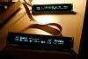
Futaba M402SD10FJ in 4-bit parallel transfer mode
Hawkeye commented on Hawkeye's gallery image in Members Gallery
 Hi Antix... thanks... it is really not 8-bit compatible, read more info and 4-bit mode code patch :) Greets, Peter
 -
welcome on board! it would be possible, but if it should be the same, then buy the axiom, will cost you way less time and money... you would also have to find a suitable keyboard.... for that cost you can get a full usb-based midi keyboard controller... on the other hand, if you plan for some extras, you can roll your own. But it takes time, and as far as I see, some PIC coding which most people on this planet don´t do for fun ;). I´d recommend to buy a decent midi master keyboard and then think of additional features you need...
-
great! thx! placing first low volume order nao :) edit: done - will keep you posted regarding the shipment speed to germany - great service and a really good idea!
-
ultra-nice shipping rates!!! can i reconsider todays order? :-) (if it is still possible - paypal refund and I try your new shipment method tomorrow ;) ) background: last time i was "handled" in a local customs office, i was very close to hurting that customs officer after an hour or so ;-) thx! Peter
-
or maybe there are some fake "glass buttons" made out of plastic out there, that can be glued to the smd tactile switch top with two component epoxy or so. I like the idea with the cutted glue sticks though, 100% macgyver :)
-
From the album: Hawkeyes MB stuff