Hawkeye
-
Posts
3,636 -
Joined
-
Last visited
-
Days Won
36
Content Type
Profiles
Forums
Blogs
Gallery
Everything posted by Hawkeye
-
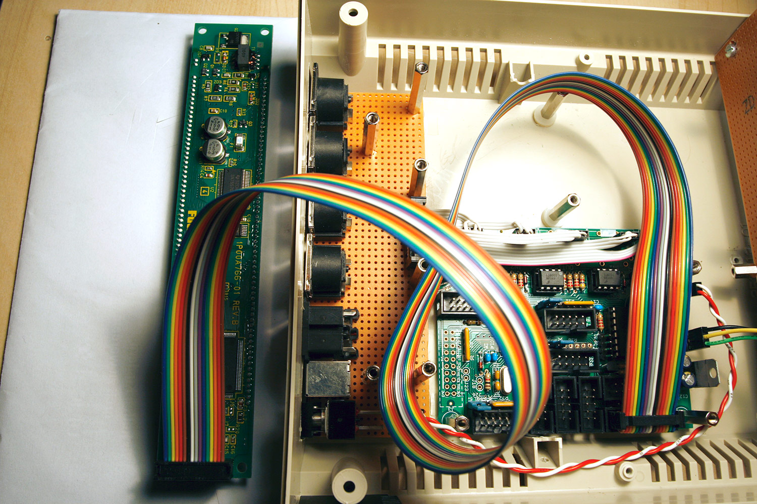
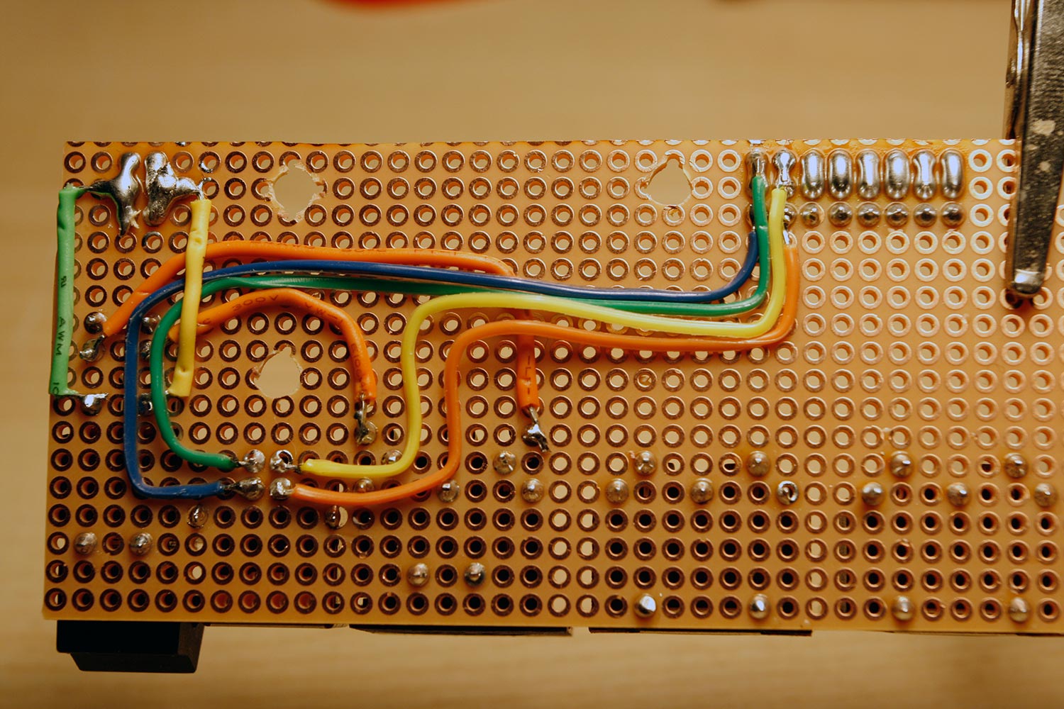
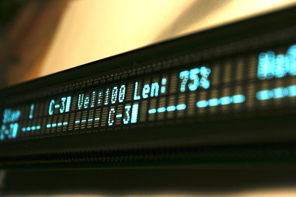
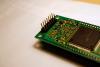
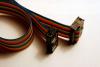
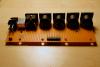
Step 10: Test a VFD Parts used: * Futaba VFD M402SD10FJ (buy two, i got mine from mercateo.com for less than 50€ per piece) * 14 pin DIL-header or 2x7 pin SIL-header (e.g. from AVI Showtech, but every electronics shop should carry this) * 16 pin flat ribbon cable (e.g. from AVI Showtech, but every electronics shop should carry this) * 2pcs 16 pin female IDC connector (e.g. from AVI Showtech, but every electronics shop should carry this) Description: Being nosey parkers, we want to quickly check how the vfds perform, so lets hook one up (even if that means, that we have to change the display cable later on). * Solder the DIL header to the backside of the VFD as shown in photo 1. * Create a display cable as shown in photo 2 - it is important to note the twist. Photo 3 clarifies things and shows how to plug-in the cable. Note, that the VFD only needs 14 pins (no backlight voltage pins 15 and 16), make sure that you plug-in the cable, so that pin 1 (marked with an arrow - see photo 1) correlates to the the first pin of your cable coming from the core32, so that the unused pins of the idc connector are on the other side than the arrowmark. In the pictures, pin-1 is the dark blue colored ribbon. Turn on the sequencer and enjoy ;-). No knobs to turn and no buttons to push yet... but very nice. You can repeat the procedure with the other VFD, of course.

-
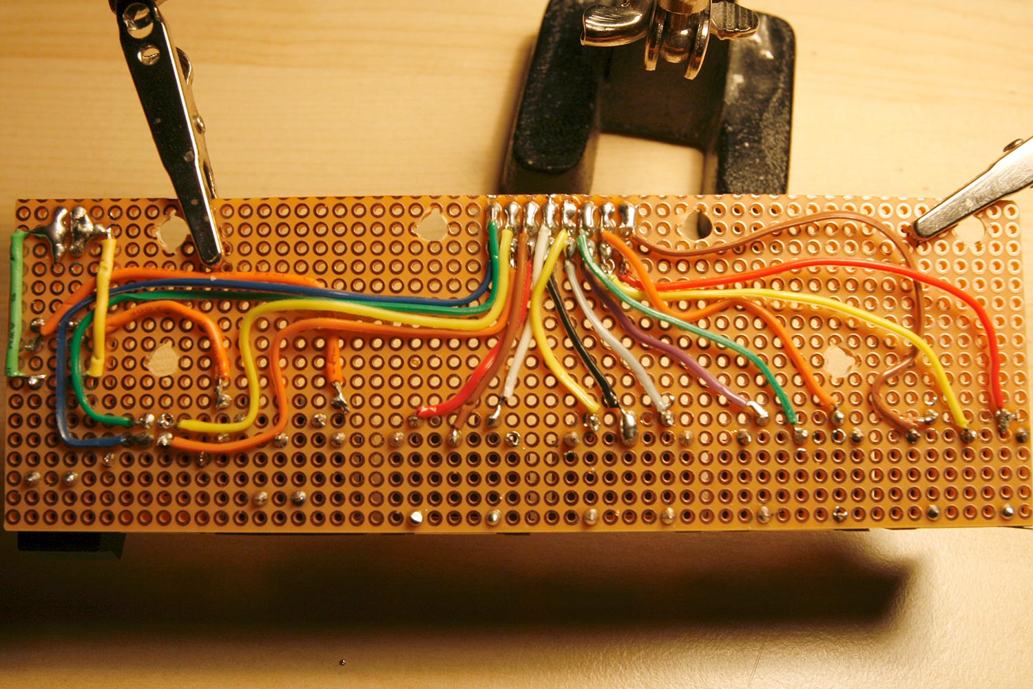
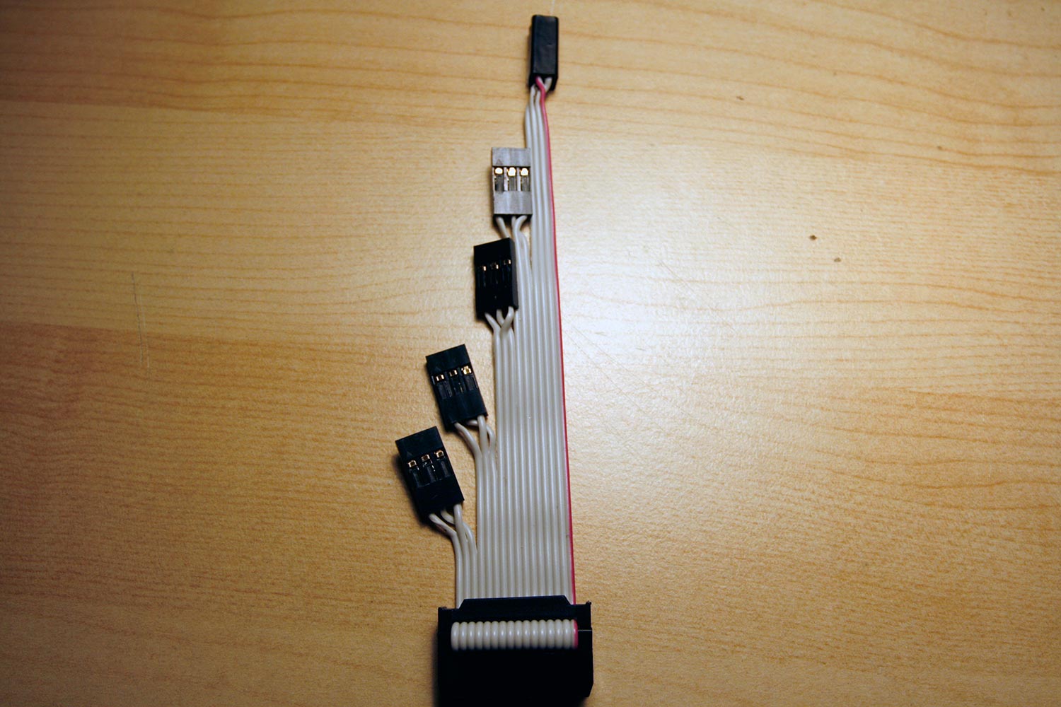
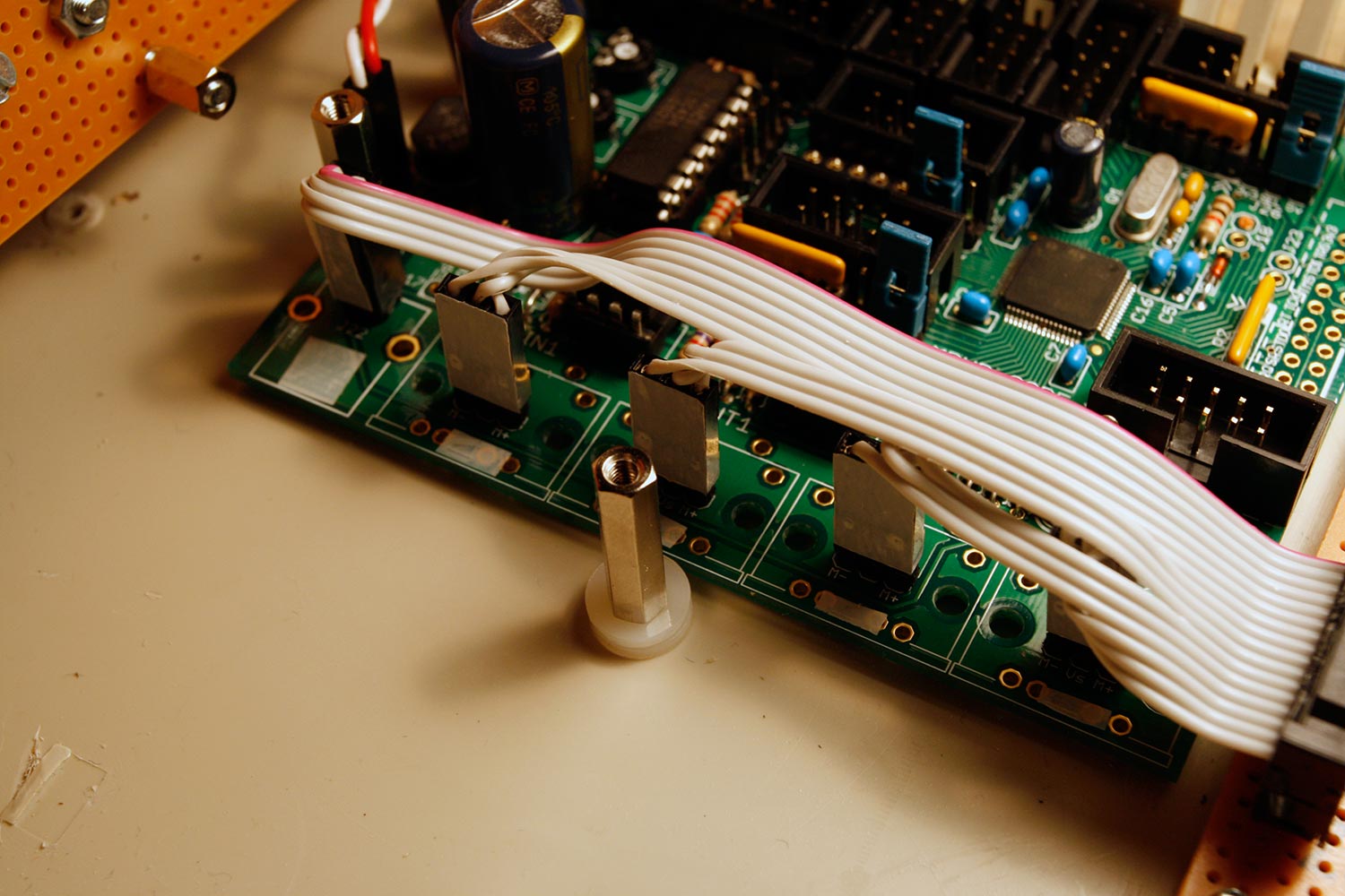
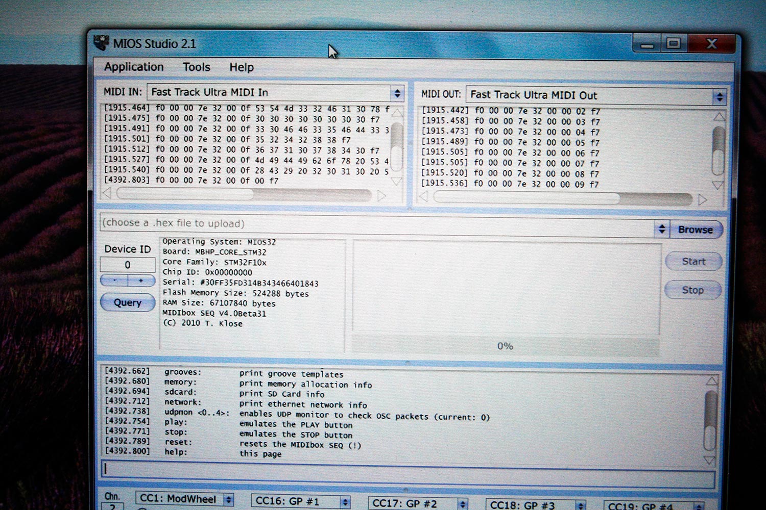
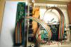
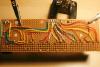
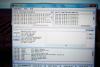
Step 9: Connecting the lower Backplane USB and MIDI Ports, Flashing MBSeq via USB, Testing MIDI Parts Used: Core32 Module (from step 5) Lower connector backplane (from step 6) 16 pin DIL-header or 2x8 pin SIL-header (e.g. from AVI Showtech, but every electronics shop should carry this) 16 pin flat ribbon cable (e.g. from AVI Showtech, but every electronics shop should carry this) 16 pin female IDC connector (e.g. from AVI Showtech, but every electronics shop should carry this) 2pcs 2-pin SIL housing (USB connector) (e.g. from Mouser) 4pcs 3-pin SIL housing (MIDI connectors) (e.g. from Mouser) 16 pcs SIL housing crimp terminals (e.g. from Mouser) A piece of colored tape to use as a connection orientation label USB Cable (for flashing and testing) 2x MIDI Cables and a computer MIDI Interface (for testing) A running version of MIOS Studio 2.x+ (for flashing and testing) Description: * Install and solder a DIL header to connect the lower backplane to the core as shown in photo 1. * Wire the USB connections using cable of appropriate length, as shown in photo 2. Keep the cables flat to the vector board. * Wire the MIDI connections as shown in photo 3. When routing cables, stay clear of the hex standoff holes. * Create a "cable tree" as shown in photo 4. Use the IDC connector to create a 16-pin plug at one end (see ). Add 2x2-pin SIL housings at the USB end (you can tape together the two sil housings to create a "quad plug"), and 4x3-pin SIL housings for every midi port. * Connect the cable to the core and the lower backplane. Turn the whole assembly over and measure connectivity between every solder point where the original connectors should have been placed on the core32 board and their real location on the lower backplane vectorboard. They should be just prolonged 1:1 and there must be no solder bridges. Take your time to check that. * When fully installed, your case should look like photo 5. You can use small pieces of tape on the connectors and on the base board to mark correct plug alignment. * Connect the USB port to your computer. Power-on the sequencer. If everything was cabled correctly, your OS should list 4 new MIDI IN and OUT ports: one USB-MIDI port pair, and three MIDI port pairs provided by the Core32. * Start MIOS studio and select the USB Midi port pair as MIDI IN and MIDI OUT. * Press "Query". The core32 delivers some nice status information, such as memory information and serial number. * In MIOS Studio select ("browse"-button) and flash ("start"-button) the MBSeqV4 app you previously downloaded from http://ucapps.de/mios32_download.html - if you are using the exact same VFDs as myself, you will need a slightly changed LCD display driver (4-bit mode) - currently it is not available in the source repository, so I attached my current version of a functional MBSeq 4.0 beta31 with enabled 4-bit LCD drivers for your convenience. More infos on the "hack" are available * After the flashing procedure, the sequencer will reboot and the MBSeq app will be executed on the core. You can now use MIOS Studio to type "help" in the command section to see some feedback from the MBSeq app itself. You can also type in "play" for a first visual inspection - the attached LED will start to flash (beat indicator) ;-). * To test the MIDI ports, disconnect the sequencer from usb and connect MIDI cables to another connected USB/Firewire MIDI interface. Wire up MIDI IN1 and MIDI OUT1 or MIDI IN2 and MIDI OUT2 to your other USB/Firewire MIDI Interface and select the USB/Firewire Interfaces´ MIDI ports in MIOS Studio as In- and Out-ports. Now press query, you should see the exact same information as was delivered before via USB, but now over MIDI. Test the other port pair, too. Photo 6 shows MIOS studio talking to the MBSeq via a MIDI Port (I used my FastTrack USB Interface). I clicked on "Query" (middle left window) and typed in "help" in the lower command window. If everything works, you have an operational MBSeq - ok ok, no control surface yet... :-) project.hex


-
the missing termination is probably not the reason for your trouble, but it is documented here: http://ucapps.de/midibox_seq/mbseq_v4_din.pdf
-
hb, TK! gustl is inbound later :)
-
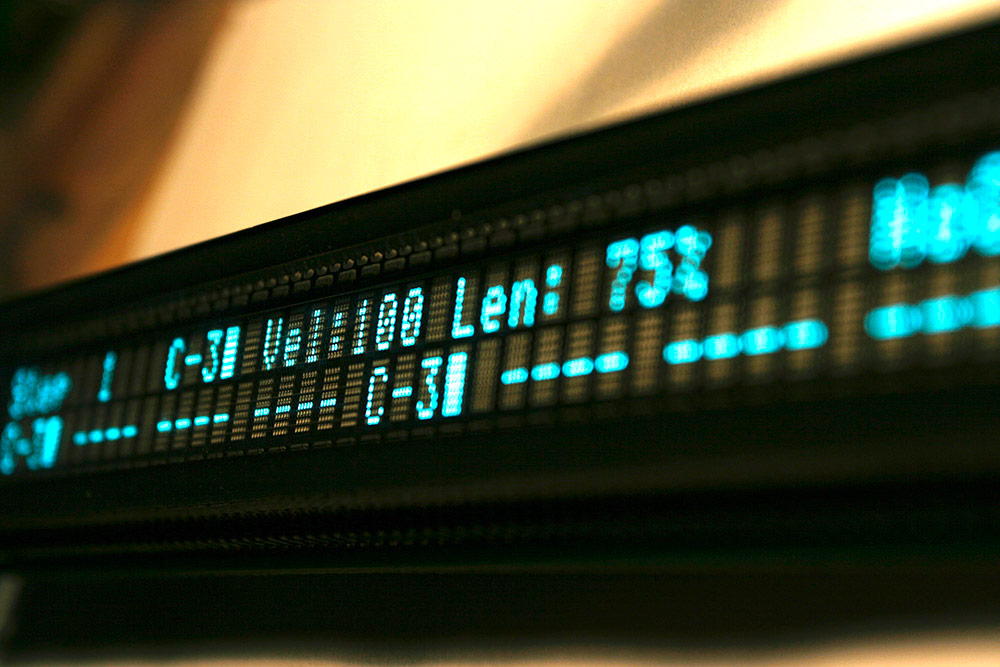
Problem solved, the display only works in 4-bit parallel mode (-> you need to switch to 4bit clcd display module and recompile your core32 app). See The display itself is exceptionally nice and there is no "ghosting delay" as my cheap led backlit lcds have.

-
LCD Character Scrambling - Futaba VFD M402SD10FJ <-> Core32
Hawkeye replied to Hawkeye's topic in Testing/Troubleshooting
:frantics: YESSS! it workz :frantics::sorcerer: haz i earned coder status nao? :rolleyes: if there is interest - i could either create a clcd4bit module or as there are only a few lines changed handle it with the preprocessor and check via #ifdef CLCD_4BIT ... svn diff and picture of working vfd is attached app_lcd_diff.txt
-
LCD Character Scrambling - Futaba VFD M402SD10FJ <-> Core32
Hawkeye replied to Hawkeye's topic in Testing/Troubleshooting
thiz only happenz when D1 is low... i am able to display a "C" for example (D1: 1 D0: 1) - i measured cables and the vfd pins, no shortage... But... I have the feeling that 4-bit mode will help. In the tech docu the motorola mode is only depicted in 4 bit mode, if that is true, those suckers... ;-)... if it works, ofc i will offer a clcd4bit driver for TK. The pinsavingz would enable the core32 to drive 3 CLCDs right? ;-) Plz get back to your diploma thesis so we can meet in Munich and have a beer ;-) -
LCD Character Scrambling - Futaba VFD M402SD10FJ <-> Core32
Hawkeye replied to Hawkeye's topic in Testing/Troubleshooting
ok, further investigation - the problem occurs reproducably in 8-bit data transfer mode for all characters where D1=0 and D0=1, so to say A, E, I, M ... they are replaced by the predecessors where D1=0 and D0=0, which are @, D, H, L... That´s why a character replacement hook won´t work... i am not able to send any char in 8-bit mode with d1=0, d0=1... that looks a lot like a bug on the vfd side... i have also switched cables and measured for unwanted bridges twice... Now investigating 4-bit transfer mode, where d4-d7 are used... -
LCD Character Scrambling - Futaba VFD M402SD10FJ <-> Core32
Hawkeye replied to Hawkeye's topic in Testing/Troubleshooting
to keep you up-to-speed, I made some progress on the toolchain side... managed to get it up and running under FreeBSD, which i prefer to code on - now this toolchain uses the gcc 4.3 compiler and i am able to get the scrambled screen outputs again instead of a blank screen - looking into app_lcd timings and if adjusting them does not work, will try out a character replacement hook... I would bet, that TKs build toolchain also still uses gcc 4.3 :-) btw., when attaching a normal lcd, the outputs are fine, so no problem on the core32 side of things... this vfd surely is a bit bitchy ;-)- but what i love in this vfd is that there is no afterglow, new characters are displayed instantly - comparing to my 9US$ LCD, this is better by magnitudes... -
Markenpräferenzen beim Bier? Ich empfehl eigentlich Gustl oder Tegernseer ;)
-
ich wär dabei, solang ich TK ´nen Kasten Bier überreichen kann ;)
-
Looks nice, the question is now where to obtain dragonskin 30 in europe ;)
-
terminator :)
-
did´cha install the arnold?
-
LCD Character Scrambling - Futaba VFD M402SD10FJ <-> Core32
Hawkeye replied to Hawkeye's topic in Testing/Troubleshooting
Please forgive my unstructured initial problem report. I´ve got 2 issues: 1) some, but not all characters are replaced by alphabetically close characters (TKs MBSeq Build) - i wanted to fix this with a char replacement hook, but then this happened: 2) builds from my toolchain behave differently than TKs builds - my display stays dark after a power cycle Thanks and sorry for double posting. -
Welcome! The MB6582 rocks, you will love it. I´ve made a for the building process of the control surface... it is not difficult at all.
-
Thanks and good luck then! I did not want to take away your last bit of free time, it is just so nice to work on a unit that you have built all by yourself, i can only recommend that :).
-
Hola, I tried to connect the abovementioned Futaba VFDs (datasheet) to the Core32... when running the current MBSeqV4 app, some characters are scrambled, it appears that always a few of the characters are replaced by different ones "close to" the original when examining the character table... an example photo is shown in The cabling is fine, i built another, shorter cable with the exact same problems. Trying to hack things, I then installed the Windows-based dev toolchain, which works fine (respect on the code documentation, svn structure and nice build system!). When I build an MBSeqV4 or the tutorial #20 (lcd test) and I power-cycle the Core, the display stays dark (the mbseq app runs though, it can be queried via mios studio). When I don´t power-cycle after flashing tutorial #20 from a TK-built SeqV4, the display stays on and shows increased garbage - it creates "animated" strange looking special characters... There seems to be a difference between my build and TKs build... when I build apps, things are getting much worse... :-( - are the any defines/environment variables which i am missing (i set clcd as lcd environment variable and the rest of the environment variables from the toolchain documentation). Edit: I suspect some timing issues... could it be that my toolchain (gcc 4.4 based) produces differently optimized code than TKs variant which is faster or slower leading to different behaviour on the vfd? I saw some loop-based sleep code and maybe that got optimized away? Thx for help! Peter
-
sorry, i was not precise, responding to buddhas question, i meant the total current of the smd leds in matrix configuration. sorry for hijacking your thread :)
-
building midiboxes before creating music is like meditating before levitating =)
-
I just tested with disconnected D0-D3 (hoping for a forced 4-bit mode), but that increased the display garbage (seems like it still uses 8-bit mode). Grounding D0-D3, while D4-D7 are connected blanks the screen. Connecting all 8 data wires looks partially good: ca 50% of characters are ok, ca 50% are "shifted" by a few ASCII digits. E.g. an "e" becomes a "d", a "C" becomes an "A". Any suggestions how to fix that? Has anyone read the thread with the partially replaced characters lately? - I searched for two hours today and cannot find it, although i know it is there - this makes me nervous :-) Thx! Would be willing to adapt an app_lcd driver, but I just don´t know yet how to start... any pointers are welcome...
-
buddha, i have none in mind yet (not ready), we should also look at the max current drain, which might be problematic in a big matrix. And, at it would be very nice to create a PCB, so that we do not have to literally weave thin copper wires.
-
they are very nice and silent, but small... and you have to surface-solder them, but this is no problem, as the pads are in the correct scale to fit on a vector board.
-
Just finished my MB-658s but issues with 6581 chips
Hawkeye replied to Rave-TZ's topic in MIDIbox SID
random mental output: * Do the 6581s now work in core 4/sid 7+8? * I don´t know how the 6581s behave, but have you jumpered the audio in headers, so that the sid audio in pin is grounded - on the 8580 i get some static noise or 50hz hum if left open, but not as extreme as you mentioned. * Are your cores installed in the correct order - 0 right ... 3 left? * Have you uploaded the same (newest version) of mb6582.hex to each core in mios studio, setting the midi jumper on the baseboard and the address in mios studio so that the right core receives midi data? -
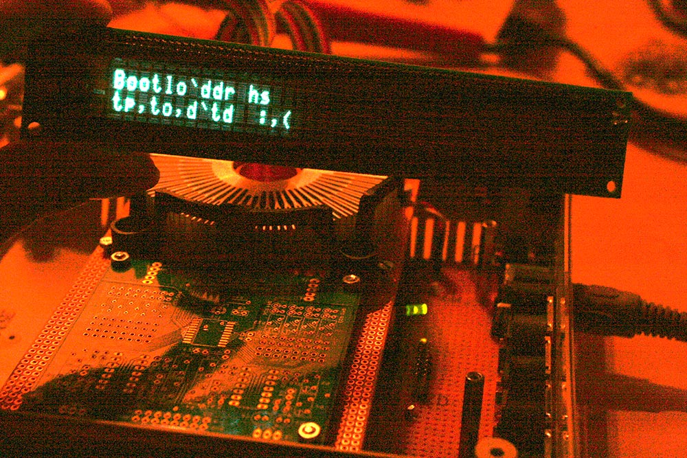
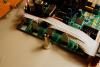
Couldn´t help and work a little bit ahead of time (the vfd mbseq photo tutorial currently lags behind a step :)) - the vfds look awesome, really really cool, something my cam is not able to capture. currently i do not have the core32 flashed with mbseqv4, so i hope the character problems are gone after the boot loader is finished... i read about these problems a time ago here in the forum, some characters were displayed as double characters... well, we will see how this can be fixed :) thanks for the encouragement, TK, i am so glad i bought them ;-) edit: unfortunately, after uploading mbseqv4 in mios studio, the problem did not go away... any hints are welcome :) btw. the display should be in motorola mode by default - it looks like some characters are shifted, e.g. "Notd" instead of "Note" and "Ahn. 0" instead of "Chn. 0".And I am sure I read about this not so long before, but can´t find it... :-(