

FantomXR
-
Posts
1,035 -
Joined
-
Last visited
-
Days Won
22
Content Type
Profiles
Forums
Blogs
Gallery
Everything posted by FantomXR
-
Yes! You got it. It's not for saving money. It depends on the size of the carrier pcb. If I create a pcb for just one display, I'd think we will be at about $1 / pcb or less. What I want is, create a schematic with a working layout for one display. Duplicating this to add more displays is not a big deal after that. Everybody should be able to create a display board that fits their needs. Maybe in the future it makes sense to step back from the LRE. It's very time consuming to solder all leds. I'm right now in creating PCBs for encoder and led rings. It has two rows with each 4 encoder on it. There is enough space to place a oled underneath every encoder and the LEDs are soldered at the manufacture. That's why I need the right schematic. So any hell would be very appreciated. Hawkeye: pls take a look at the sheet of the oled. There are schematics that show the parts needed. There also the filtering caps inside.
-
I'd guess that it wouldn't be that hard to implement the needed features if we'd have the eagle files of the LRE available :-)
-
Like i said: let's step back from the MBProgrammer. If we have a working layout which works fine with NG, other layouts can be easily adapted.
-
Okay. Than I'll stick to the standard wiring for now. Changes can be done in the future. Btw: SPI is not natively supported of Midibox, is it? The carrier board wouldn't bring any advantages. So. I'm still up for creating a layout. Could anyone say which of those two schematics is the right one? I can post them later on just click on the link on the starter post and scroll down. It's there.
-
If you can guide me to the carrier pcb on alien press, this would be nice. My idea was not to create something that only works for MBProgramma but for all other applications. Do you have a wiring layout for using the SPI? What are the advantages?
-
SMD soldering is not a problem here. We could also let all SMD parts solder at the pcb manufacture and just put the display in. Anyway...I need the right schematic :)
-
Totally!! And no mounting holes on the wrong place ;) Pls check the other thread I just created.
-
Hey folks, in another thread those displays were mentioned: http://www.buydisplay.com/default/datasheet-128x64-oled-module-spi-0-96-inch-graphic-displays-white-on-black I think it could be great, to create a PCB that fits those displays. In the end it's more flexible and even cheaper. So, those displays will need some kind of circuit to run fine. I took a look into the spec-sheet and there are two schematics. One it for "Vcc generated by internal DC/DC" and the other one "Vcc supplied externally". I wonder which one is correct in our usecase. I'd guess it's the external-one? Seeed-Studio has those displays in their PCBA service btw. So, if there is a interest on this, I'd offer to create such a PCB and put the eagle-files online, so everybody would be able to create their own displays-panels with an easy connection to midibox. But at first I need to make clear, which schematic is correct. Thanks, Chris
-
Pay attention: These displays would need a circuit, to power the display. It's not done with solder a connector to a PCB and connect it directly to midibox. Check the spec-sheet of the displays. The circuit is inside. BTW: I'd also love to use those displays as in the end it might be much cheaper to produce the carrier boards and to buy those displays separately.
-
Liebe Leute, neben dem DIN, welches in einem anderen Thread schon Besprechung findet, soll es hier nun um die SMD Version des DOUT Moduls gehen. Das Problem bei dem DOUT ist, dass es verschiedene Bestückungen gibt. Das Layout, welches ich nun entworfen habe, sieht einen ULN2803 vor, sowie jeweils 8 Widerstände für die SRs. Theoretisch könnten diese Widerstände weggelassen werden, wenn der ULN2803 als Treiber benutzt wird (so zumindest meine Erfahrung), aber zu viele Versionen anzubieten wird wohl letztlich zu teuer. Der ULN2803 schluckt auch in der SMD-Version ziemlich viel Platz... deshalb konnte ich es nicht so wirklich schön anordnen. Ich komme damit auf eine Gesamtgröße von 31x53mm. Ein paar Traces muss ich noch ziehen und Eagle gibt mir den Keepout-Fehler... die Widerstände seien wohl zu eng beieinander. Das habe ich aber auch noch enger gesehen. Hier kann man sicher auch Widerstandsnetzwerke zurückgreifen. Auch hier sind die Stiftleisten so angeordnet, dass zwei Flachbandkabelverbinder gerade so nebeneinander passen sollten. Mehr Platz einsparen ist hier also nicht möglich. Meinungen?
-
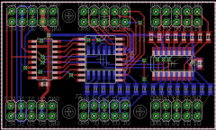
From the album: PCBs
-
You will run into problems. The pinheader are too close together. You won't be able to plug in two ribbon cables. Anyway: Looks good. Do you have a routed version? //edit: Your layout is nearly impossible to reproduce. This could work for the DOUT Module. But not for the DIN. The resistors don't lead to the pinheaders. The layout I already created is the smalles possible if you want to stick to normal ribbon connector Also wäre super, wenn jemand den Schaltplan verifizieren könnte. Danke!
-
If you need some help, I can offer to design a wooden housing if you are interested. Just PM me. //edit: not only design but also manufacture it. I have the necessary stuff here.
-
Liebe Leute, es hat ein wenig länger gedauert. Hier nun im Anhang das Layout und der Schaltplan. Wäre super, wenn jemand sich zumindest den Schaltplan nochmal ansehen kann, um zu schauen, ob dort alles korrekt ist. Vielen Dank! DIN.zip
-
Great project! BTW: using OLEDs is the cheapest way to add displays to the project in my opinion. I have a vendor on aliexpress who sells them pretty cheap. I ended up with less than 5€ per piece. I won't get a 16x2 Display for that price and OLEDs are even nicer. But there are several versions out there of this OLED. They may have different connectors / pinnings. Pay attention to that. Is it planned to add the LRE-Boards to Tim's PCB shop? Otherwise it would be hard to rebuild those device. Anyway: Keep up the good work! :-)
-
Ah, totally right... it's only CC. Something else: If I have an EVENT, which calls a meta script, for example to toggle between value 50:70, does a Snapshot save the status of this meta-script? I assume "no" because it's not in the NGC. Am I right?
-
Hey TK, just a short question: Does NG support MSB/LSB settings for program changes?
-
Great! Sounds like a plan. Thank you!
-
Oh... I'm sorry... really? Seems this was not in my head anymore! Thanks for remembering me! BTW: do you see a simple chance to forward this value to LEDs? At the moment I think this could be pretty difficult and of course this function is just needed in conjunction with keyboard-use. I don't see any other usecase... Next step: Creation of a test-surface to check all those nice features.
-
Hey TK, I have another request. Now it has something to do with keyboards. Now as MIDI learn works (but still needs to be tested on my side), this might be easy for you to implement: By default a keyboard that features NG has a range of 0:127. Of course you could set split-zones by entering it into the NGC file. But it would also be nice to have either two knobs to control the range, one knob for the highest, one note for the lowest note, or to do it via MIDI-learn by pressing the key on the keyboard. Anyway: Except of working with a keyboard this could be a useful feature even with standard controllers... set ranges on the fly sounds like a nice add. Do you think this would be possible? In advantage to this the range could be forwarded to a tricky LED-matrix (one led per key) to show the actual setting. I don't know if it's hard to do. Just let me know what you think about it ;) Thanks! Chris
-
Pete, I know the SL instruments very well... and they are quite often buggy. The bugs Michał reported are not new to me :) But you are right. I could be the contacts... but it might be easier to try another software first.
-
Hi, I will try to help you, but you should learn about ucapps bei yourself. This is more helpful than ask for every detail. The connection to the AINSER is really easy. I'm sure you figure it out. If you need any help anyway, pls ask again. The problem with my PCBs is, that the MIDI-Connectors aren't working. USB is no problem. So if you just need USB, this will work. If you need the MIDI sockets, you'd need to go with the official STM-Core. But I could send you the adapter. Just send me a PM with your details. Thanks!
-
Hi Aki, I think I can help you with your project. First of all you need a core-module. I suggest to go with the STM32F4 Board, because this one is up2date. You can get the PCB from smashtv / avi-showtech or I can send you one, depending on where are you located. Second you need a DIO Matrix module. This you can also get at smash or from me. Than you will need adapter. You are a lucky guy because I designed a adapter, that's made for plug and play. On one side you plugin the keyboard connectors and on the other side 1:1 connectors to the DIO-Board. Nothing else needed. For analog signals like aftertouch, pedals, wheels, etc. you will need an AINSER module. I suggest to go with the AINSER8, because you won't need more. You have two aftertouchstrips... one is for the black keys and one for the white keys. If you have any further questions, just let me know.
-
Another chance is to use optical sensors. But I think this may take quite a bit of time to implement this feature.
-
Awesome! I need to test it!! :-) Thanks TK! This seems to be a major feature. I have another request :-) but that we should cover in another topic :-) Yeha! Have a nice weekend.