novski
-
Posts
460 -
Joined
-
Last visited
-
Days Won
5
Content Type
Profiles
Forums
Blogs
Gallery
Everything posted by novski
-
Thanks for those reports. @monokinetic i don't find a Software called PICKit3 as i do for PICKit2. Instead i found MP-LAB-X. What software do you use exactly? Does MP LAB X suit the needs of a Midibox Bootloader? Thanks in advance novski
-
Hi I broke 2 of my 3 PIC 18F452. sad.. :rolleyes: So i wold like to be able to Burn my MF_NG Cores myself. I Then whent to the uCapps site and read about burning and the MBHP_Burner. Because i don't have a Parallel Port i wold like something witch a USB plug instead. I searched in the Forum and found this: Altitude refers to a Programer on E-bay witch i was able to find on the Distributor on net. this one: http://www.piccircuit.com/shop/pic-programmer/56-ica03-usb-pic-programmer-set.html But im not shure about the Software to the burner-tool. I think Brenner5 will not work. Does somebody have experience with a USB Burner? best regards novski
-
Yes. Thats why i have those used Buttons... I kept a bag of old used ones, but im thinking of making a single Buttonpad of 3x8 Buttons for my Controller... I like those because of the Cap on top where i can place a name foil... So it wold be great to find the Manufactory of those Rubberbuttons...
-
Those Buttons are from a Studer Console and they look really good to me. I wold like to know where they made those and if there is a chance to design my own somehow... Does somebody know who can make such cool rubber buttons?

-
I have no idea... Cortex M3 Production started in 2004.
-
There is a User Project on Wiki about DMX. --> http://www.midibox.org/dokuwiki/doku.php?id=midiboxdmx best regards novski
-
Hi Monsta That sounds good. Are those boards ready made to be connected to a DIN-Matrix?
-
Hi Im generally interested in those Buttons. They look like factory made -no DIY- or so. where did you get those buttons from? I wold like to get a 8x3 Rubber Buttonpad from somewhere... Best Regards novski
-
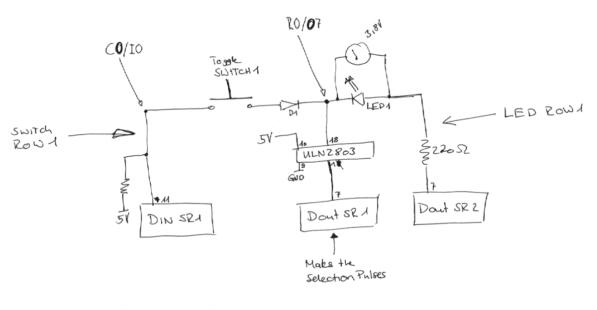
Thanks. Now it works. I had a LED the wrong way and used the DINx4 with 220R also in the Selector lines - sr_dout_sel1=1 (...) The Link mentions just 3 SRs. Thats why i tried to build a better version than i had working. # HW definitions: DIN_MATRIX n= 1 rows=8 inverted_sel=0 sr_dout_sel1=1 sr_din1=1 DOUT_MATRIX n= 1 rows=8 inverted_sel=0 sr_dout_sel1=1 sr_dout_r1=2 # note: actually the sr_dout_sel1 in DOUT_MATRIX could be removed, # since DIN_MATRIX already outputs the selection pulses there # this is just for the case that somebody copy&pastes the definition... I layouted it like on this schematic: It seams to work but: The LED seams to be not as bright as it can be. Am i doing that right? Best Regards novski
-
Hi I made my self a breadboard test of a Button and LED Matrix. Im not able to make it work as i wish. So i ask for a sample config of a 8x8 button_matrix with a 8x8 LED_Matrix wich for testing wold lit the LED 1 by pressing Button 1 and turn it of by depressing the same button. button_matrix sr_din1=1 sr_dout1=1 LED_matrix sr_dout1=2 sr_dout2=3 best regards novski
-
phenomenal! so i can save the access time by using RAM instead of SD storage... :D Great. Thanks a lot!
-
Hi I just tested your suggestions. They work! I tryed to make several buttons work. But i found out that i have to make a section for each button, witch i think is not the right way to go. How wold you configure 24 Buttons in *.NGR? Thanks novski Edit: don't need full table, just maybe a example of 3 buttons...
-
Im using it with SAC a software audio mixer for realtime live applications. Www.softwareaudioconsole.com A bit a special usage... Im not working on requests yet. Im trying to send only... Best regards Novski
-
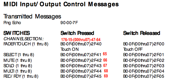
Hi John E. Finster Thanks for the hint to the .NGR File. This works really! I started to make me a File with 24 Buttons and tried some topology that doesn't seam to work, can you say me how you wold make a second, third button work? There is a other thing i can't understand. If i touch a Fadercap i generate a similar message. But it seams to have a Ping going with it as well witch is described in this document. The thing i can't follow is the number 68-75 (90 68 7f) Here is a copy of the messages transmitted by touching 2 Fadercaps in follow: [30356.400] b0 0f 00 Chn# 1 CC# 15 = 0 [30356.401] b0 2f 40 Chn# 1 CC# 47 = 64 [30356.401] 90 68 7f Chn# 1 Note On G#6 Vel:127 [30356.512] b0 0f 00 Chn# 1 CC# 15 = 0 [30356.512] b0 2f 00 Chn# 1 CC# 47 = 0 [30356.512] 90 68 00 Chn# 1 Note Off G#6 (optimized) [30427.985] b0 0f 01 Chn# 1 CC# 15 = 1 [30427.986] b0 2f 40 Chn# 1 CC# 47 = 64 [30427.986] 90 69 7f Chn# 1 Note On A-6 Vel:127 [30428.065] b0 0f 01 Chn# 1 CC# 15 = 1 [30428.066] b0 2f 00 Chn# 1 CC# 47 = 0 [30428.066] 90 69 00 Chn# 1 Note Off A-6 (optimized) how can i find out what a number i have to transmit with the Select or Mute Buttons... Thanks for any help.. -And the help you already done! Novski
-
Hi I have trouble to figure out how to emulate the MotorMix Controller. I captured the Values once with MidiOX and had a version working on before MB_MG came up. But now im not able to trace that back and make it work with MB_NG. The main problem is that MotorMix seams to send a CC:15 value 0 event by pressing a (toggle-) button and by releasing it it sends a CC:47 value 67 (that wold be what happens when solo 1 is pressed.) How can i send two different CC with one Press/depress? greets novski
-
Thank you, Thorsten!
-
True. I read about that once and coldn't follow. Do you know how it handles those 14bit (214=16384)? Because 27 means 128(?). My Display always counts from 0 to 127 max / top. how high is the transmitted resolution over midi really?
-
Am i wrong thinking MF_NG has to operate in Motormix emulation anyway...?
-
Question to John E. Finster: Is it posible to make meters with reaper? (i thought you told me once you use reaper...?)
-
Well, those "controll" Surfaces are actualy also Soundcards. So they have a direct Audio-Stream and those meters can be activated by Audio directly in the controller. Even when the metering data is distributed on LAN. the Protocol described in the Link of JohnE.Finster is Layer 2 so OSC isn't (please correct if false...) a option as well. You wold need to write your own driver on top of a midibox core... On the last page of that topic you can read that several guys tried to get the EuCon Protocol to make their own thing but didn't even get an answer. Avid owns the protocol and keeps it secret it seams... but it wold be a nice thing to have... :phone:
-
well im not so shure in this. I think it shold be possible for MBHP_NG to assign 16 LEDs. you will have to try. Im asking my self how to get to the Data of Metering. I thought that the Protocol supported through ProTools does not provide Metering..? Are you using Midi ore RS232 (somehow???) in ProTools?
-
Thats a good Question. I assume that you cant combine 2 Matrixes together so there is a max. of 16 LEDs per Matrix. For 32K you will need 2 Matrixes. http://www.ucapps.de/mbhp/mbhp_doutx4_ledrings.pdf for 32 Encoder: http://www.ucapps.de/mbhp/mbhp_dinx4_16enc.pdf for 32 OLED: http://www.ucapps.de/midibox_ng_manual_lcd.html scroll to the bottom. There you can find nice Schematics, Fotos and the Details.
-
Hi Nick M Did you ever tested your faders with the Mios Studio MF_NG Program? It seams to me that the motor is inverse or the 0%/100% Pin is miss connected to Wiper. Test the two buttons top and bottom. If the fader goes up and down and up again it wold seam to me all right... Here is a Connection diagram: http://dl.dropboxusercontent.com/u/29658831/midibox/MF_NG/MF_NG_connection_diagram.pdf Check if the connections are right and be aware that the motor has to be on top. If you whant to have the motor botom sided you need to inverse both. Motor A/B and 0%/100% of your fader... best regards Novski
-
I droped a PIC18F452 with MIOS v1.9G (ID 17) and an undefined app on it in my MF_NG modul and can't connect. this is the error message: ------------------------------------------------------------------------------------------ Detected MIOS8 and MIOS32 response - selection not supported yet! Check MIDI IN/OUT connections and Device ID! ------------------------------------------------------------------------------------------ Well im connecting over the LPC17 Core (ID 0) to the MF_NG module and i can connect to an other PIC18F452 with MIOS v1.9G(ID 19). At the same time i see the input Monitor running Hex codes until the MIOS Studio crashes. i don't have a MBHP_Burner so im curious how i can solve that... Thanks for any ideas Best Regards Novski
-
i just ordered some by mouser the other day... thats the code: 652-4606X-1LF-47K or for Germany is Segor maybe cheaper... segor ordernumber: SIL 5x 47k