novski
-
Posts
460 -
Joined
-
Last visited
-
Days Won
5
Content Type
Profiles
Forums
Blogs
Gallery
Everything posted by novski
-
Do i understand right? Mirroring = It lets the LEDs go "ON" in the opposite direction (shift-register Outputs go Low in Opposite direction as without) Inverting = It swaps the row and selector shift registers Best Regards Novski
-
Hi TK. Wonderful! it was the Inverter... The Polarity is equal to fairlightiiis pcb. But i designed just 15 LEDs because for Audio Panorama functionality i want a Middle "single" LED. Now the Middle point is decreased to left. I expected it to increase to right because the LED missing there. (my LEDs are like fairlightiii's from left to right) Is that because of the Inverting? Thanks a lot! novski
-
I have problems with my LED Matrix. I built it upon the Schematic of Fairlightiii's pcb but with just 8 Encoders and LED Rings. By turning one of the Encoders all LEDs around the other Encoders go on, but the LEDs around the Encoder i turn don't. And the brightness of the LEDs increase by Turning all the Encoders to 127. Don't know where to start searching. The PCB is correct, i checked that. this ist my config .ngc for testing: RESET_HW LCD "%C" LCD "@(1:1:8)OLED1" LCD "@(2:1:8)OLED2" LCD "@(3:1:8)OLED3" LCD "@(4:1:8)OLED4" LCD "@(5:1:8)OLED5" LCD "@(6:1:8)OLED6" LCD "@(7:1:8)OLED7" LCD "@(8:1:8)OLED8" # Buttons configuration EVENT_BUTTON id=1 fwd_id=LED:1 type=NoteOn key=24 lcd_pos=1:1:1 label="^std_btn" EVENT_BUTTON id=2 fwd_id=LED:2 type=NoteOn key=37 lcd_pos=2:1:1 label="^std_btn" EVENT_BUTTON id=3 fwd_id=LED:3 type=NoteOn key=38 lcd_pos=3:1:1 label="^std_btn" EVENT_BUTTON id=4 fwd_id=LED:4 type=NoteOn key=39 lcd_pos=4:1:1 label="^std_btn" EVENT_BUTTON id=5 fwd_id=LED:5 type=NoteOn key=40 lcd_pos=5:1:1 label="^std_btn" EVENT_BUTTON id=6 fwd_id=LED:6 type=NoteOn key=41 lcd_pos=6:1:1 label="^std_btn" EVENT_BUTTON id=7 fwd_id=LED:7 type=NoteOn key=42 lcd_pos=7:1:1 label="^std_btn" EVENT_BUTTON id=8 fwd_id=LED:8 type=NoteOn key=43 lcd_pos=8:1:1 label="^std_btn" EVENT_BUTTON id=9 fwd_id=LED:9 type=NoteOn key=36 lcd_pos=1:1:1 label="^std_btn" EVENT_BUTTON id=10 fwd_id=LED:10 type=NoteOn key=37 lcd_pos=2:1:1 label="^std_btn" EVENT_BUTTON id=11 fwd_id=LED:11 type=NoteOn key=38 lcd_pos=3:1:1 label="^std_btn" EVENT_BUTTON id=12 fwd_id=LED:12 type=NoteOn key=39 lcd_pos=4:1:1 label="^std_btn" EVENT_BUTTON id=13 fwd_id=LED:13 type=NoteOn key=40 lcd_pos=5:1:1 label="^std_btn" EVENT_BUTTON id=14 fwd_id=LED:14 type=NoteOn key=41 lcd_pos=6:1:1 label="^std_btn" EVENT_BUTTON id=15 fwd_id=LED:15 type=NoteOn key=42 lcd_pos=7:1:1 label="^std_btn" EVENT_BUTTON id=16 fwd_id=LED:16 type=NoteOn key=43 lcd_pos=8:1:1 label="^std_btn" EVENT_BUTTON id=17 fwd_id=LED:17 type=NoteOn key=36 lcd_pos=1:1:1 label="^std_btn" EVENT_BUTTON id=18 fwd_id=LED:18 type=NoteOn key=37 lcd_pos=2:1:1 label="^std_btn" EVENT_BUTTON id=19 fwd_id=LED:19 type=NoteOn key=38 lcd_pos=3:1:1 label="^std_btn" EVENT_BUTTON id=20 fwd_id=LED:20 type=NoteOn key=39 lcd_pos=4:1:1 label="^std_btn" EVENT_BUTTON id=21 fwd_id=LED:21 type=NoteOn key=40 lcd_pos=5:1:1 label="^std_btn" EVENT_BUTTON id=22 fwd_id=LED:22 type=NoteOn key=41 lcd_pos=6:1:1 label="^std_btn" EVENT_BUTTON id=23 fwd_id=LED:23 type=NoteOn key=42 lcd_pos=7:1:1 label="^std_btn" EVENT_BUTTON id=24 fwd_id=LED:24 type=NoteOn key=42 lcd_pos=8:1:1 label="^std_btn" EVENT_BUTTON id=41 fwd_id=LED:41 type=NoteOn key=43 lcd_pos=1:1:2 label="^std_btn" EVENT_BUTTON id=41 fwd_id=LED:25 type=NoteOn key=43 lcd_pos=1:1:2 label="^std_btn" EVENT_BUTTON id=42 fwd_id=LED:42 type=NoteOn key=36 lcd_pos=2:1:2 label="^std_btn" EVENT_BUTTON id=43 fwd_id=LED:43 type=NoteOn key=37 lcd_pos=3:1:2 label="^std_btn" EVENT_BUTTON id=44 fwd_id=LED:44 type=NoteOn key=38 lcd_pos=4:1:2 label="^std_btn" EVENT_BUTTON id=45 fwd_id=LED:45 type=NoteOn key=39 lcd_pos=5:1:2 label="^std_btn" EVENT_BUTTON id=46 fwd_id=LED:46 type=NoteOn key=40 lcd_pos=6:1:2 label="^std_btn" EVENT_BUTTON id=47 fwd_id=LED:47 type=NoteOn key=41 lcd_pos=7:1:2 label="^std_btn" EVENT_BUTTON id=48 fwd_id=LED:48 type=NoteOn key=42 lcd_pos=8:1:2 label="^std_btn" # Encoder configuration ENC n= 1 sr=4 pins=0:1 type=detented2 ENC n= 2 sr=4 pins=2:3 type=detented2 ENC n= 3 sr=4 pins=4:5 type=detented2 ENC n= 4 sr=4 pins=6:7 type=detented2 ENC n= 5 sr=5 pins=0:1 type=detented2 ENC n= 6 sr=5 pins=2:3 type=detented2 ENC n= 7 sr=5 pins=4:5 type=detented2 ENC n= 8 sr=5 pins=6:7 type=detented2 # LEDring configuration DOUT_MATRIX n= 1 rows=8 sr_dout_sel1= 7 sr_dout_sel2= 0 sr_dout_r1= 8 sr_dout_r2= 9 # Encoder events EVENT_ENC id= 1 fwd_id=LED_MATRIX:1 type=CC chn= 1 cc= 24 lcd_pos=1:1:4 label="^std_enc" EVENT_ENC id= 2 fwd_id=LED_MATRIX:2 type=CC chn= 1 cc= 25 lcd_pos=2:1:4 label="^std_enc" EVENT_ENC id= 3 fwd_id=LED_MATRIX:3 type=CC chn= 1 cc= 26 lcd_pos=3:1:4 label="^std_enc" EVENT_ENC id= 4 fwd_id=LED_MATRIX:4 type=CC chn= 1 cc= 27 lcd_pos=4:1:4 label="^std_enc" EVENT_ENC id= 5 fwd_id=LED_MATRIX:5 type=CC chn= 1 cc= 28 lcd_pos=5:1:4 label="^std_enc" EVENT_ENC id= 6 fwd_id=LED_MATRIX:6 type=CC chn= 1 cc= 29 lcd_pos=6:1:4 label="^std_enc" EVENT_ENC id= 7 fwd_id=LED_MATRIX:7 type=CC chn= 1 cc= 30 lcd_pos=7:1:4 label="^std_enc" EVENT_ENC id= 8 fwd_id=LED_MATRIX:8 type=CC chn= 1 cc= 31 lcd_pos=8:1:4 label="^std_enc" # we've a single MBHP_MF_NG module with 8 motorfaders # It has to be configured for Motormix protocol! MF n=1 enabled=1 midi_in_port=IN2 midi_out_port=OUT2 chn=1 ts_first_button_id=2001 config_port=USB3 ################################################################################ # on motorfader movements EVENT_MF id= 1 fwd_id=ENC:33 type=CC chn= 1 cc=32 range=0:127 lcd_pos=1:1:5 label="^std_mf" EVENT_MF id= 2 fwd_id=ENC:34 type=CC chn= 1 cc=33 range=0:127 lcd_pos=2:1:5 label="^std_mf" EVENT_MF id= 3 fwd_id=ENC:35 type=CC chn= 1 cc=34 range=0:127 lcd_pos=3:1:5 label="^std_mf" EVENT_MF id= 4 fwd_id=ENC:36 type=CC chn= 1 cc=35 range=0:127 lcd_pos=4:1:5 label="^std_mf" EVENT_MF id= 5 fwd_id=ENC:37 type=CC chn= 1 cc=36 range=0:127 lcd_pos=5:1:5 label="^std_mf" EVENT_MF id= 6 fwd_id=ENC:38 type=CC chn= 1 cc=37 range=0:127 lcd_pos=6:1:5 label="^std_mf" EVENT_MF id= 7 fwd_id=ENC:39 type=CC chn= 1 cc=38 range=0:127 lcd_pos=7:1:5 label="^std_mf" EVENT_MF id= 8 fwd_id=ENC:40 type=CC chn= 1 cc=39 range=0:127 lcd_pos=8:1:5 label="^std_mf" # on touchsensor event (first id has been specified in the MF configuration above) EVENT_BUTTON id= 2001 type=NoteOn chn= 1 key=0x68 range=0:127 lcd_pos=1:1:6 label="^std_btn" EVENT_BUTTON id= 2002 type=NoteOn chn= 1 key=0x69 range=0:127 lcd_pos=2:1:6 label="^std_btn" EVENT_BUTTON id= 2003 type=NoteOn chn= 1 key=0x70 range=0:127 lcd_pos=3:1:6 label="^std_btn" EVENT_BUTTON id= 2004 type=NoteOn chn= 1 key=0x71 range=0:127 lcd_pos=4:1:6 label="^std_btn" EVENT_BUTTON id= 2005 type=NoteOn chn= 1 key=0x72 range=0:127 lcd_pos=5:1:6 label="^std_btn" EVENT_BUTTON id= 2006 type=NoteOn chn= 1 key=0x73 range=0:127 lcd_pos=6:1:6 label="^std_btn" EVENT_BUTTON id= 2007 type=NoteOn chn= 1 key=0x74 range=0:127 lcd_pos=7:1:6 label="^std_btn" EVENT_BUTTON id= 2008 type=NoteOn chn= 1 key=0x75 range=0:127 lcd_pos=8:1:6 label="^std_btn" Any Ideas? Thanks novski
-
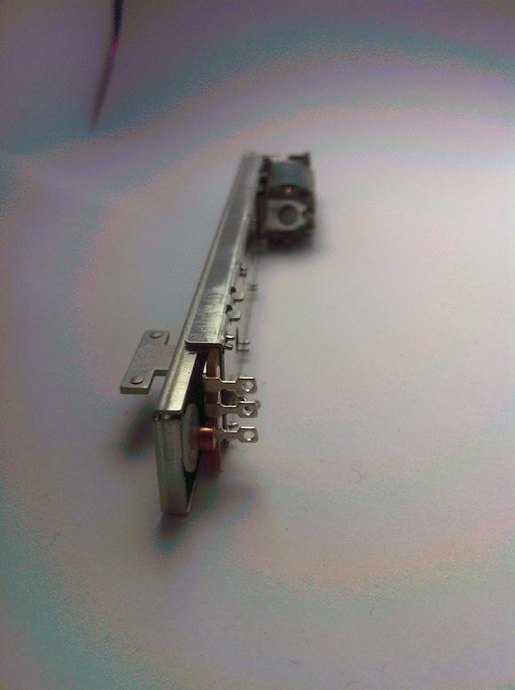
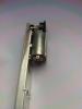
Hi Im Selling 100 pice ALPS Motorfaders RSAON11M9AOK - Link to the Datasheet Price is 15 Euro p. pice & Shipping. I will check the shipping cost if you send me a PM with Quantity and Address. -for more than 30 Pice = 13 Euro p. Pice & Shipping. It looks like this: Best Regards Novski

-
Yes. I will somehow. But i have to get to a end of prototypeing bevor... Stay in Touch. I will maybe just make a bulk Order someday...
-
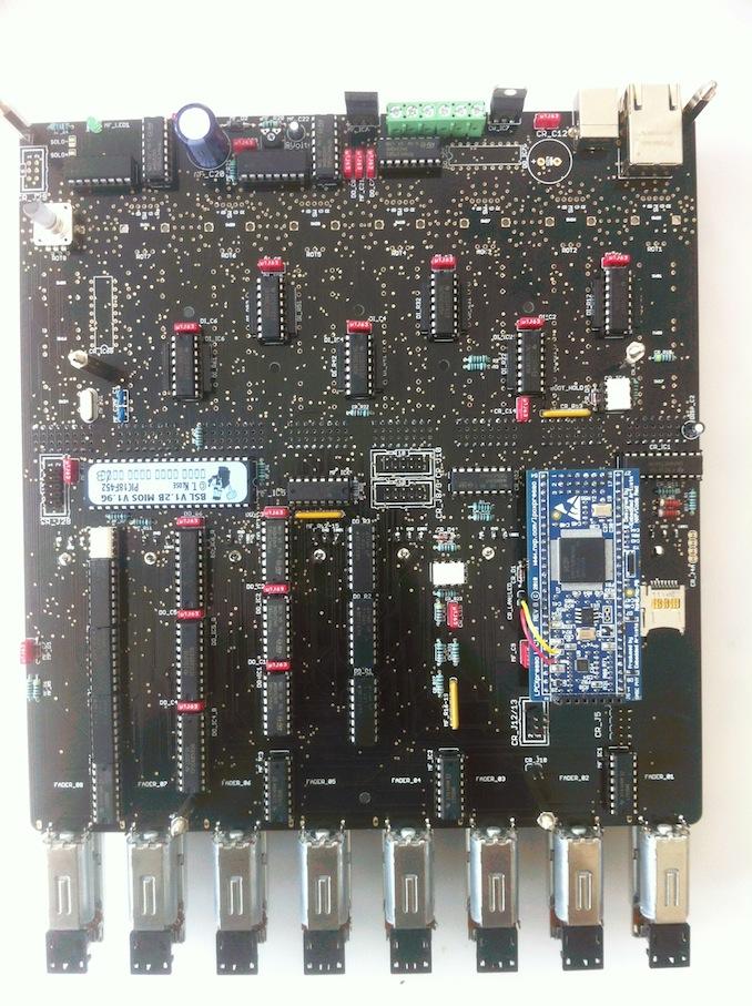
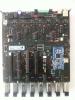
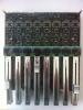
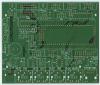
Well manisteinn, i am going this way sice a Year now. I have Prototype 2 on my Table now and will be able to make a functional up to May or so... But i took the 0K with Soldering Pins because they are not so far away from the PCB witch makes it easyer to find a Switch that fits on top of the PCB. I selected a MEC G5 Iluminated button,a OLED Display, a Bourns PEC12 Iluminated encoder and made a LED Ring around each of the 8 Encoders. So what i'm now Testing is a 8 Fader with 3 Buttons per Channel and one Encoder with Matrix. And as a goodie the 0.96" OLED Display for each channel. It was quite hard tho get that on one Board with a width of 22x22 cm. Attached a Pic of the unfinished Test. Im planing to make a slave pcb as well so a daisy-chain of 3 more (4x8=32 faders) is possible. But i have to do one by one... Did you already evaluate a button to the A07 type of Fader yet? Best Regards novski
-

Sweet tool for buying electronic components online!
novski replied to keves's topic in Parts Questions
Thanks keves! Interesting possibility i will try it soon. -
@TK. A Button assigned as "08" doesn't work and gives out a error in comandline of MIOS Studio. A button assigned as "01"-"07" works. Same for Button and LED "8" - witch is recommended.. Every 8 Buttons or LED added shows the same behavior. Like 8, 16, 24, 32, 40, 48, 56, 64, 72 i didn't test more... for readability i appreciate the "01" form, because it makes the aligning more adequate for my eyes. I double checked it with 2 Cores, to me it seams to be a App thing... It seams to be so since midibox_ng_v1_018.
-
I asked this question in december 2012 it can be found here: And was further discussed in this Topic: Main advantage was to have a Display for each Fader/Channel. But in the mean time TK and Duggle implemented a way to hook up 64 Displays to one Core. You can Read about that here: The schematic about the connection between multiple Cores is to find here: http://www.ucapps.de/midibox_ng/multicore_interconnections.png But i don't think anybody ever really tried this exept maybe TK. How many Faders do you need? Best Regards novski
-
:yes:
-
well, isn't out there in the world of components a shift-register with integrated 74HC04??? :D
-
I just thought about the ability to stay in the usual NG app system and to stay easy upgradeable.. It wold be nice if there wold be a way to change the Hardware instead of the Software... Is a shift register always the same or is there a possibility to find a register that works inverse?
-
AH. OK. Thanks Ilmenator. I hoped it wold give a easy MIOS File browser way.. But i will set up the toolchain and try that. (i recently had to change my Mac and since that wonderful NG with Filebrowser is working so fine i didn't needed it until now..) :phone:
-
Is there a possibility to let the DIN and/or the DOUT react inverse? Background: Usual DOUT LED is lit by switching HIGH on the Output O0-7 of the HC595 Shiftregister. I wold need a possibility to switch to LOW so i can inverse the Polarity and Connect the Cathode towards the Shiftregister and the Anode to the 5V supply. And the same for DIN. Connecting the Resistor Network to GND and switching the Supply "VD" towards the Inputs I0-7 of the HC165 Shiftregister wold inverse the reaction. So it wold be nice to have a possibility to inverse the reactions in Software... is that possible in some way? Thanks novski
-
unfortunately no... :sad: just with 3FTL Mec Switches...
-
it cold be because i use a 8Gb Card... FAT has some restrictions for files above 4Gb...
-
Hi Lamouette Look, i got it Today! It looks brilliant! I can send you a PCB for 5$...
-
I just recognized that this behavior only seams to be when i format the card with MIOS Studio. As soon i Format it with a PC it creates the files correct. And the Mios File Browser displays them nicely as Default.NGC/NGL/BIN Anyway i have a question to the Midibox_NG connected to a MF_NG Modul over Midi 2 on LPC1769. I can't manage to get connection to the PIC. Witch has device ID:17 After uploading the MF CC Test im searching since 2h for information about the Routing i may have to do. hopeless.. i don't have a clue. why does this command doesn't work in Mios Studio? set router 1 SRC:USB1 off DST:OUT2 all Unknown or invalid MIDI input port!
-
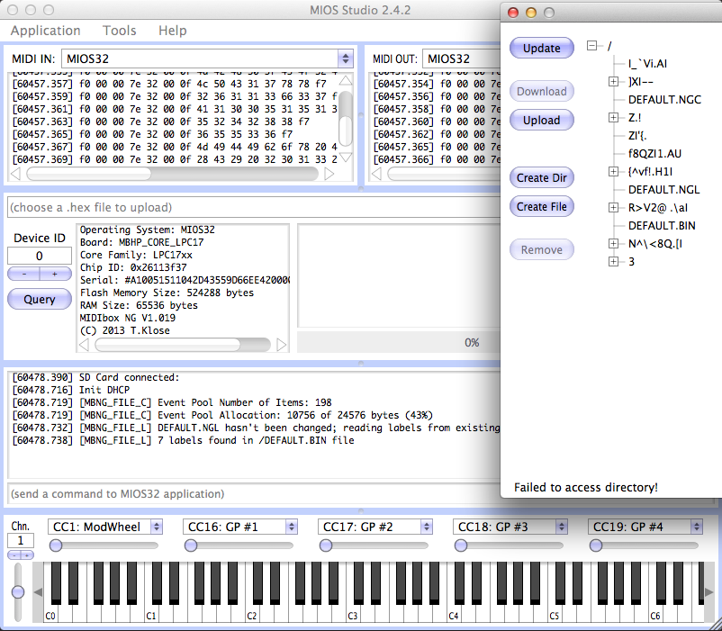
Hi TK, first thanks for your answer. I tryed to format the sd card in MIOS 2.42 Comandline but unfortunately nothing happened. So i thaught i cold just remake the hole thing. I first connected the LPC Link and loaded the Bootloader in LPCXresso then loaded and configurated the MIOS Bootloader v1.011. So i had the "Bootloader is up to Date :-)" Screen show up on my Display. Then i Loaded the midibox_ng_v1_020 and tried to format the SDcard again. But it was the same as on my first attempt... The Display still shows "READY." but LED2 on the LPC1769 Board goes out. And nothing happens. Im not sure if that is a Hardware issue... Maybe its also a Problem with the Size of my uSD card, its 8Gb (i had that laying around, but it may have a to large memory?) Update: After Formatting the Card trough a Cardreader in "Festplattendienstprogramm from OSX" it loaded the .NGL file successful and it works now. -So there must be something wrong in the sdcard_format procedure... MIOS comandline FormatSDcard.rtf
-
or if you want i can send you one piece of the PCB that has the Display wire crossed over... You wold have to cross each second wire for the right connection... I don't want to earn anything on those... if you send me a PM with your address i can get information about the postal cost and send it for that price...
-
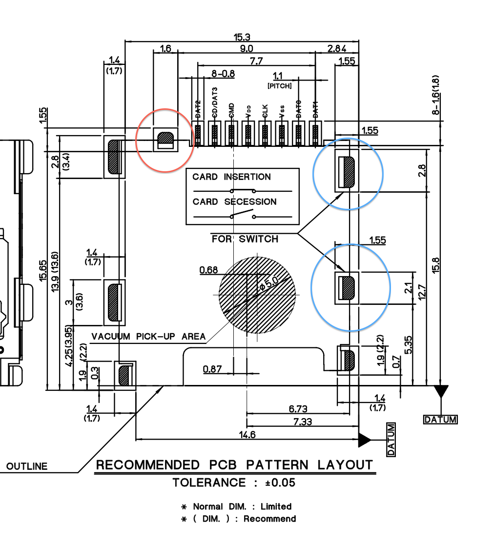
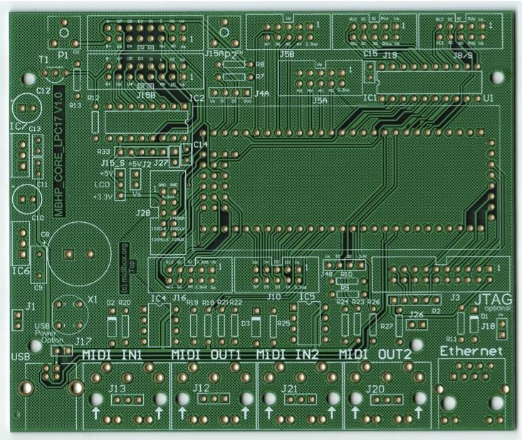
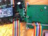
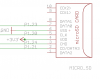
My self designed PCB shows a strange behavior in reading the microSD memory card. It seams to me like the USB connection is OK, because i was able to load the Bootloader and the midibox_NG app normally. But now to configure my setup the memory seams to have a failure reading the microSD card. I have an idea that it cold be a problem with the Switch pins i didn't mention in my design (they are al to GND). The red pin connects to GND as soon a card is inserted. The two Blue pins close as soon the card is inserted without connecting to GND. Did anybody ever see something similar like picture one shows?

-
I routed the pins to wrong Connections... It died right on the first attempt... The SCS Board is a trial to get in to PCB Ordering and making... I will sell the left over Boards, as soon as i have one that works... :-) Are you interested in one?
-
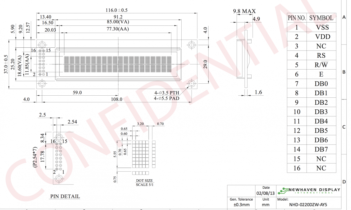
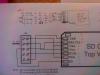
Well then that wold mean that the Display is supposed to be Connected on the Top side. I can't understand that, because with a hight of 4mm the Connector will always block the mounting to a frontplate...

-
I have 1 x 5pin SIL Cables for each: DIN one and DOUT one... Pin 1 one the J8/9 is GND. Do you have this PCB from SmashTV?
-
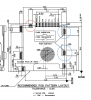
do you have the DOUT / IN PCBs with 4 registers upon? the ones i got from SmashTV have a DIL 10Pin Header and the DIN are to be connected to the Front Row and the DOUT to the Back Row. DOUT are Connected to J8 and DIN to J9. did you already see those schematics: http://ucapps.de/mbhp/mbhp_doutx4_32leds.pdf http://ucapps.de/mbhp/mbhp_dinx4_32buttons.pdf