novski
-
Posts
460 -
Joined
-
Last visited
-
Days Won
5
Content Type
Profiles
Forums
Blogs
Gallery
Everything posted by novski
-
The "Wannenstecker" is mounted to the Top. The last picture of my first post shows it... i can't follow...
-
Well i tried to consider that. but i think thats not my problem. If i draw a Schematic with Pin#1 conected to Pin#1 on the Header it shold always connect it the right way arround. I then checked the positions of the Headers and found them to be right. The header is on the Bottom side (mirrored in the properties). The Display on Top. Is it possible that the Pinheader on the Core Board is wrong? (i have the Core PCB from midibox-shop.com) if you look at the Scan i made befor i soldered it you can see that the Pin 1 of J15A is not identical with the Pin 1 on J8/9.
-
:no: I killed mine... have to get an new one...
-
Thanks ilmenator That is indeed possible. So my Display is dead... good, but how come the connecter is false? The library i used is the eagle standard: con-ml, ML16. But i can't find a fault in the package or in my schematic.
-
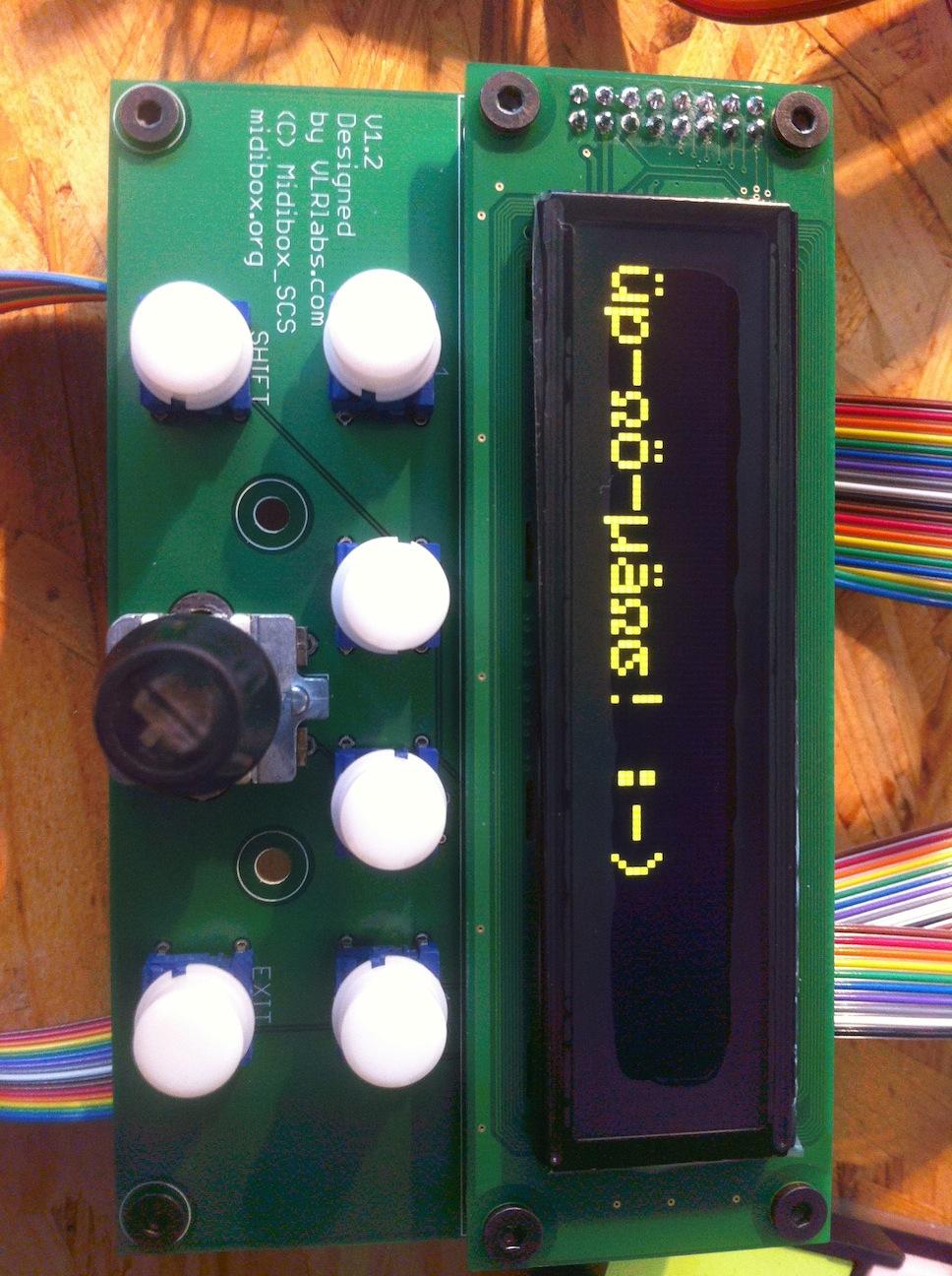
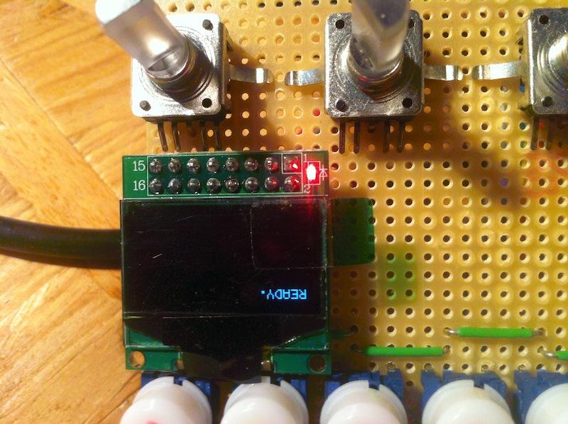
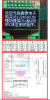
I tryed to make a Board for the SCS. Actually a simple thing, but i got a strange failure i can't locate. I drawn a Schematic with Eagle witch Simply connects the Display to a Pinheader - 1:1. But now i noticed that the Connections at the Core to my Board are Mirrored. So Pin 1 has 5V and Pin 2 GND. I then Made single Connectors to the Connection J15A and Crossed every pin from upper row to lower and vice versa. That way the display runs, but still has some weird scrambled characters. So i Connected my already running 2x16 OLED and rebooted. As you can see in the Attachment there it shows the full words correctly. I checked every pin twice and just can't understand that problem. Edited a more clear Photographic of the 2 connections. Thanks for any help...


-
I have the Newheaven one and tested it already. You can see it here: link But i think without any reprograming the SCS is made for a 2x20 Display. I ordered that 2x20 type OLED from Newheaven last week and it should arrive tomorrow or so. As soon i have it working i will make you a Photo of it.
-
Is your Schematic correct? I see the same symbol after the PSU as before. To Test you can measure GND (after PSU) to Earth. How much Ohms do you measure between those 2 Pins?
-
wow. that oshpark sounds great! 5$ for each square inch PCB and getting three for it is fabulous. Thanks for sharing that link.
-
Are you using the direct USB connection to the Core or a USB to Midi interface? - because there is a blacklist of interfaces that don't transmit sysex data correctly. Maybe its because of that... You can find it also in the Wiki area... Im also working with OSX over USB Core connection and don't have those experiences about a not responding MIOS Studio nor Core... Best Regards Novski
-
maybe this can help... http://www.midibox.org/dokuwiki/doku.php?id=mios
-
@ Ilmenator: i think exactly same. This Midibox Project is huge and im always delighted to see people build stuff as big as a Lightning console or a Harrison Audio Desk. @TK. to summarize the Question above, for SSD1306 Displays its possible to combine these three lines to one single connection...? RS -DC (Coming from LPC17CoreModul J15A) RW -SDA -D1 (Coming from LPC17CoreModul J15A) E -SCLK -D0 (Coming from LPC17CoreModul J15A) And if so, how wold you name that single wire? Thanks a lot.. novski
-
 absolutely hot!
 -
I just realized that the shift register is connected to the same J28 as the additional lines 9-12 are. And thats what you mentioned in you second last post... - It enables the shift - register by activating more then 12 OLEDs in Bootloader... sorry i got confused by the schematic of CLCD Displays and SSD1306...
-
Thanks TK for your help. One more Question, is it maybe possible to enable the Shift register also after just 8 Displays? Best Regards novski
-
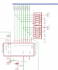
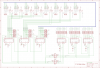
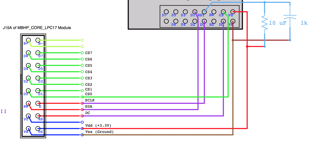
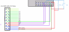
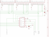
Hi, its me again... I have problems with the connection of the SSD1306 over an additional register. Am I ling right by connecting the CS lines with the Register Outputs described as E3-E10 on the schematic of LCDs? SDA,SCLK,DC are all connected together is written in the mbhp_lcd_ssd1306_multiple_mios32.pdf but are they also al connected to RW,E,RS on the core together? That sounds a little bit strange to me... The Schematic of Multiple LCDs is showing the RW line as not "doted" so im now really confused.. http://ucapps.de/mbhp/mbhp_lcd_nx2x20_mios32.pdf VSS -VSS (Coming from LPC17CoreModul J15A) VDD -VDD (Coming from LPC17CoreModul J15A) RS -DC (Coming from LPC17CoreModul J15A) RW -SDA -D1 (Coming from LPC17CoreModul J15A) E -SCLK -D0 (Coming from LPC17CoreModul J15A) E3 - E10 - CS on Displ 1-8 (Coming from Additional Register connected to J28) Can somebody verify that for me? The Second Question i have is to the Cap and Resistor. Is it necessary to place a Cap and a Resistor for each Display or is one enough for 8 Displays in a Row? I added a Snapshot of my Eagle schematic for better understanding... Thanks novski
-
unbelievable... Thanks a lot! Edit: I found a failure on the schematic of one SSD1306 (http://ucapps.de/mbhp/mbhp_lcd_ssd1306_single_mios32.pdf) -> Pin CS10 is written as CS01.
-
Is it possible to turn a Display 180° in Software? :rofl: ( i made a bad mistake...)
-
Hmm. I already made my board. Thats bad... Should have tested it bevor trusting a chinese font... ;-) The encoder are from bourns, i have got them from mouser and the name is PEL12T. http://www.bourns.com/data/global/pdfs/PEL12T.pdf They are not cheap. Some day, maybe i will make a bulk order here but until now im afraid of the lnvestment... Best Regards Novski
-
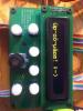
Are your Displays also 180° turned? The label on the PCB and the Display doesn't correspond. Did i made a mistake in the Wiring? cant understand. because the aliexpress site showed it the way it is labeld...

-
I think you have to load the Bootloader with the LPCexpresso software and the board we like to cut off - then over USB ... After that, load the MBNG via Midi... (sorry, i can't check because i don't have my board by me right now...)
-
Hmm... Sounds great! What are the limitations with GLCD because of ram? Thanks TK!
-
Does TK's implementation of SSD1306 also work with the MB_NG? http://www.ucapps.de/mbhp/mbhp_lcd_ssd1306_multiple_mios32.pdf
-

Replace fadercontrollers in Digidesign Control 24 with MBHP_MF_NG´s
novski replied to Teig1's topic in MIDIbox HUIs
Hi Teig1 Your lucky! With those Powersupplys you are in a good position. And all thoughts are correct. Yes you will need the Core module, it will give you access to conect to your DAW over the USB connection witch doesn't need any drivers. It connects over Midi-over-USB. There will be no need of OSC for your proposal. You may need to use the HUI Protocol because of ProTools (if thats your DAW?) So your Setup wold be a LPC32_Core connected to MF_NG over one of the 4 Midi Ports (i think TK. suggested Midi3 somewhere in this forum, i just can't find it anymore...) anyhow its possible to connect over every Midi-port... After chaining all the MF_NG, return to the Input of the same Midi-port... I think to understand its easier with a schematic...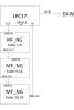
-
Hi while waiting for the upcoming multi display informations :thumbsup: - i made a Standard Control Surface PCB. I Ordered a Prototype Yesterday. It should reach me in a cuple of days. As soon its running i will publish it here. So SmashTV can sell them... (if he want to...) Cheers! novski
-
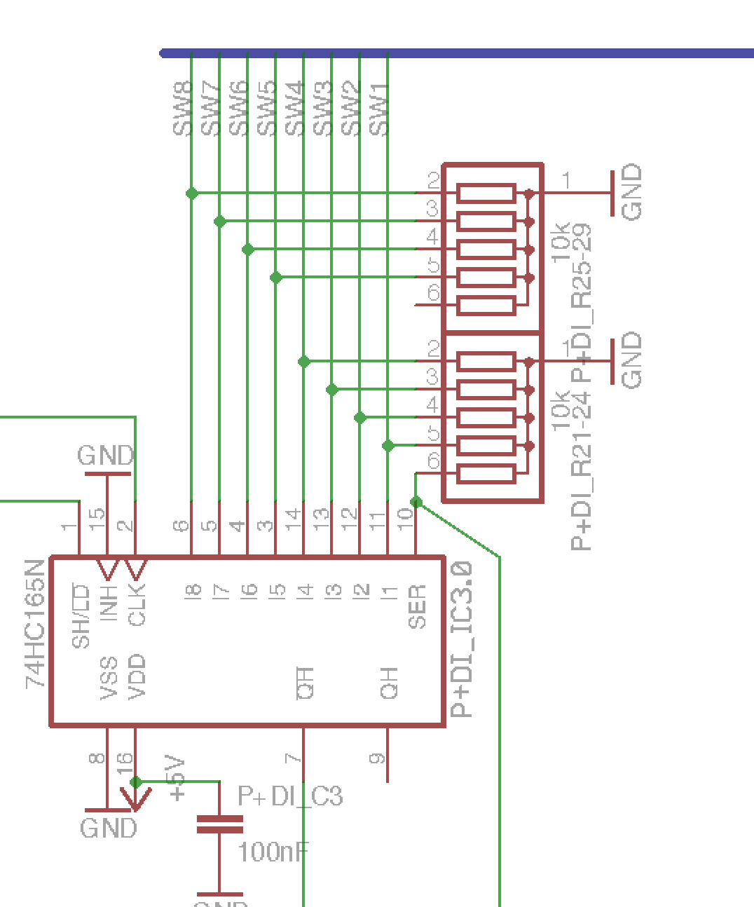
Hi again! Thanks for your advice. I went over the Schematics again and noticed in the Datasheet of 74165 that there is a inverted output on that part. So i think your solution is the best. To go sure i drawn it new. Is this corresponding with your thoughts? I attached a snapshot of the part and added the full schematics of my Encoder Board i want to build... I will test this on breadboard somewhere around new year. Thanks for the help! Edit: Better open that one in separate Window. Its to big for container...