dwestbury
-
Posts
274 -
Joined
-
Last visited
-
Days Won
26
Content Type
Profiles
Forums
Blogs
Gallery
Everything posted by dwestbury
-
Yes, I did try with and without my overdrive pots. I even shunted the audio-ins to ground to try and rule out any incoming noise as a possible root cause. Although, if the issue were actually noise or distortion, I would still expect the output volume level of SID 1 module to be similar to my other SID Modules? If you listen to my sound samples in the earlier post, you'll hear that Core 1 is both distorted and extremely quiet? Maybe this is a clue to the problem? That's a reasonable set of assumptions to pursue... I'll take a stab at reflowing the crystal, shift register sockets, relevant pin headers, etc. Basically everything in the data comms path...
-
I've been able to play around with my 3 properly functioning Core / Sid modules, which has been great, but the issues with Mod 1 are driving me bananas... Adding to the process of elimination, I just swapped out the two 74HC595s in U3_SID1 and U4_SID1 and the Neutrik Audio jack in J21, but... I still haven't found the culprit... Now I'm left thinking that I may have nicked a trace under a socket somewhere or even torn a pad from all the desoldering? (Uhg...) Thanks @Noise-Generator - let me know If anything jars your memory...
-
Hi again and thanks for pitching in! Yes, the sound from both SIDs is equally impacted from the SID1 mod. i can confirm that both the 9v and 5v levels are perfectly stable on both sockets and I've just swapped T1_SID and T21_SID for new BC547s, but still no luck unfortunately? I should also add that my newbie soldering is far from perfect, but I've been looking feverishly at every neighboring spot for cold joints, and making small touch-ups, etc. This one definitely has me puzzled...
-
Not sure what I did to completely mangle my Core 1 and/or SID 1 modules, but both MIDI comms to MIOS and audio are totally skewed now (UHG!).... Starting with the Audio Issue... SID modules #2 - 4 still sound perfectly fine (quick n dirty example below) https://drive.google.com/open?id=1FcfTqcUriYw4KaTXh1OSesTP9RLqs5_i ...But I've somehow managed to destroy the sound coming out of SID module 1?? https://drive.google.com/open?id=1tYVHFEG5-MbfYCJQZLcDfbC6LaOJ9Hk- Here's what I've done so far to try to fix this debacle... 1) Swapped SIDs chips around from other modules, but every SID sounds terrible when plugged into SID module 1 2) Swapped the filter caps (C1_SID1, C2_SID1, C21_SID1, C22_SID1) with brand new, tested 22nf metal film caps (I'm using all 8580R5 SIDs in my build) 3) Swapped the 10uf electrolytic caps that connect to J21 for audio out (C5_SID1 & C25_SID1) 4) Reflowed all joints under the Neutrik Audio out jack at J21 5) Reflowed all the solder joints on both SID sockets for SID1 Mod (U1_SID1 and U2_SID1) 6) Reflowed all the solder joins on the socket for for Core1 Mod (U1_Core1) 7) Burned a brand new PIC and swapped into Core1 ...Nothing has helped, so I'd really appreciate any insight...
-
Nice list! One I’d like to see added is the great sounding SID implementation that Gideon from the Ultimate 1541 / Ultimate 64 project (https://ultimate64.com/) has made with a Xilinx FPGA. I don’t think he’s been persuaded to consider selling it as a separate product yet however. I hear that SwinSID ultimate is very good, but they’re nowhere to be found and the creator has gone a little mad from what I understand (https://www.facebook.com/262253294115914/posts/798860600455178/?d=n&substory_index=0) Regular SwinSIDs are cheap as chips and seemingly easy to come by (eBay, etc.), but there’s lots of complaints about sound quality online. What’s the verdict on the ARMSID? I haven’t heard much about them? Cheers.
-
At €79, the FPGASID feels a little price-prohibitive. You get 2x SIDs for that price, but the installation into a real C64 is a bit convoluted. Did @TK. finalize a design that actually bypassed the need for a SID module? That would potentially raise the value in my mind...
-
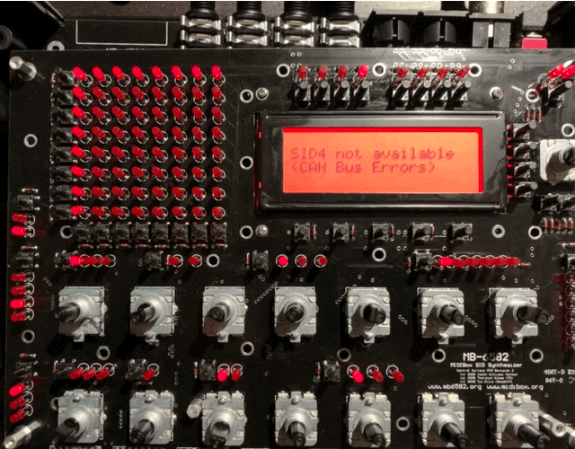
[PROBLEM SOLVED] Quite embarrassed to admit that the issue was not related to the electronics at all, but rather the false assumptions I made while trying to figure out how to setup the firmware on my PIC Core modules. I thought that changing the PIC device ID (applying device_id_0X.hex through MIOS) was the last step in the firmware deployment process, but I still needed to add the setup _mb6582 hex, after the device ID change. It's interesting to note how the device responds with CAN Bus Error when it the firmware is incomplete. Now I'm happy to say that all core modules are working perfectly... wheew... Yet another lesson learned... Finally off to *jam* with this thing!
-
I was seeing an error on startup which read "SID 4 not available (CAN bus errors)", along with a flashing top row of LEDs and flashing left column. I searched the forum and found this thread, which gave me some direction: http://midibox.org/forums/topic/13270-sidx-not-available-can-bus-errors-after-wiring-mb-6582-cs/#comment-119958 Specifically this comment from Wilba: So, I disconnected my LCD from the control surface and the flashing LED issue went away, so I must have been shorting the tactile switches behind the control surface. However, I'm still getting the same error whenever I try to access any SID module other than SID1... For reference, I can confirm that all of the D1_COREX diodes are in place, as well as R80. I've reflowed them to be sure the solder joints are good, but still no luck... Perhaps I should replace the diode under Core1? Other suggestions? Appreciate any insights.
-
The sammichSID only contains one SID module (called SID module 1 or just SID 1), but this module supports two SID chips. If your sammichSID came with some preinstalled patches, you can step through them to hear the stereo separation (assuming you're using a stereo TRS audio out cable as opposed to mono TS cable). If not, you can find a great collection of patches here: https://github.com/midibox/mios8/tree/master/apps/synthesizers/midibox_sid_v2/presets You can use the Sysex librarian built into MIOS Studio to install them using your MIDI interface: http://www.ucapps.de/mios_studio.html The control surface menu will allow you to intentionally activate or deactivate SID chips, but the default behavior is to play from both. The first steps guide in the user manual explains how to read the display: http://www.ucapps.de/midibox_sid_manual_l.html
-

Building the MB-6582 Control Surface - Photo Tutorial
dwestbury replied to Hawkeye's topic in Tips & Tricks
To me, the JB Weld bit is way tougher than the electronics ;-) Keeping fingers crossed that I don't make an absolute mess of it... -Darrell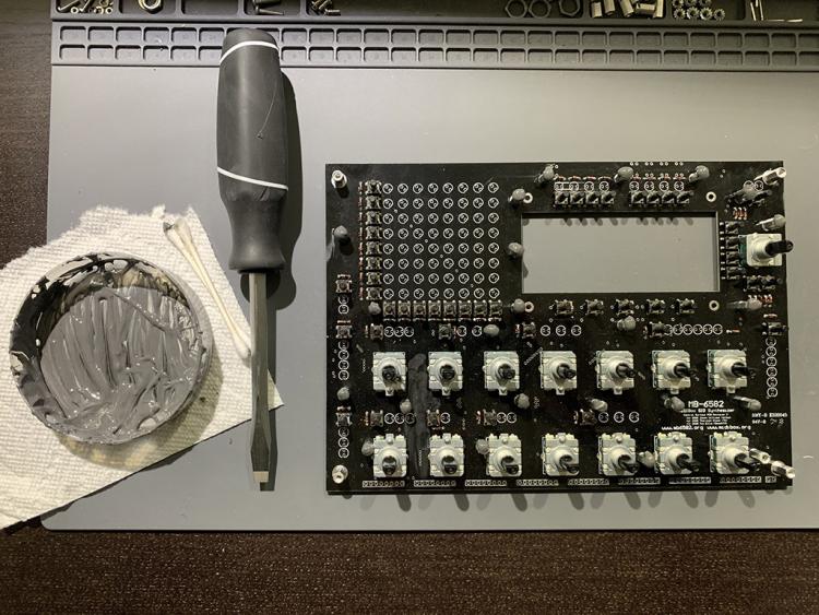

-
Connecting two posts that inevitably crossed into the same territory... After completing the steps above to create the Master Core Module, I stumbled around a bit more to understand how to change device ID’s for the slave modules... All the required steps are outlined here... http://midibox.org/forums/topic/21261-pic-programming-question/?do=findComment&comment=186267
-
@Noise-Generator you are of course right my friend.. I spent way too much time trying anything and everything, except what was most obvious and directly in front of my face... Lessons learned... Fortunately, now I can say that I've walked through the entire end-to-end process of creating the Master and Slave PIC Cores, including bootloader, MIOS OS & MB-6582 specific firmware, as well as setting the proper Device IDs. I documented the experience here in case anyone else is interested: https://1drv.ms/w/s!AtmSvwylfFJaggnN1TtalEzGQK1C?e=sRlAiG (MS Word format). Cheers and thanks again!
-
Totally understood regarding the hard work... I really like what you've done though and I'd love to buy this panel set from you... PM me if we can make that work. Cheers, -Darrell
-
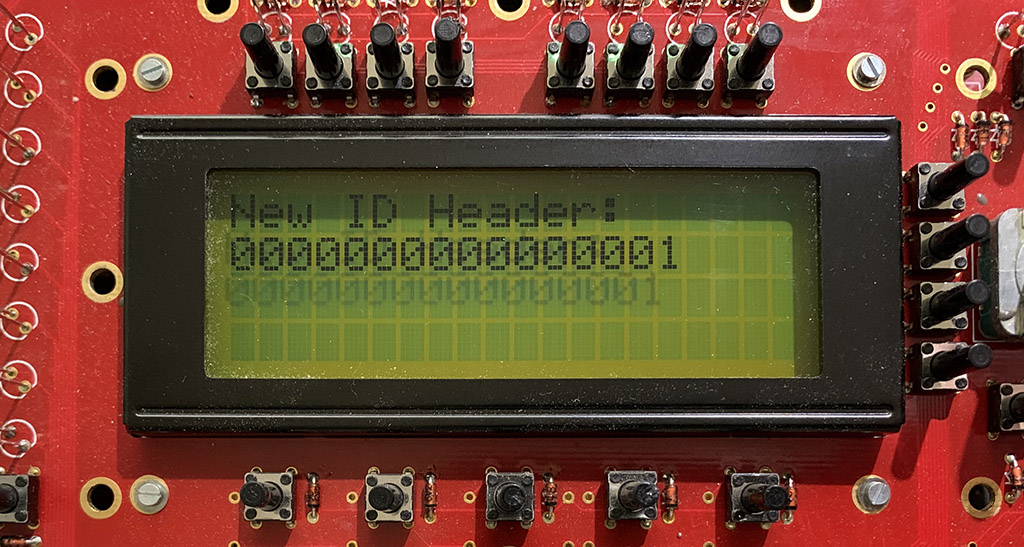
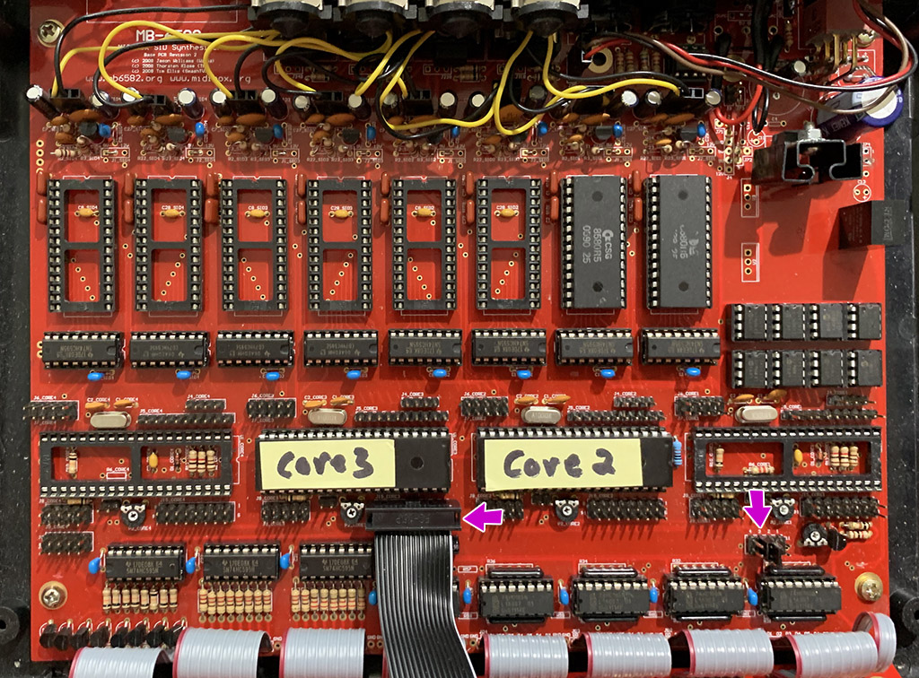
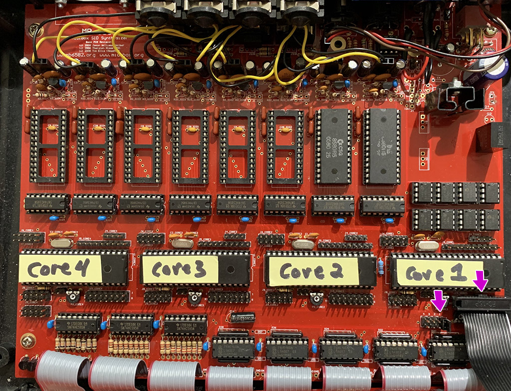
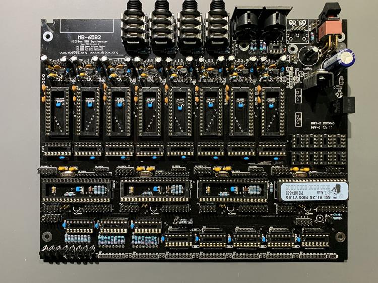
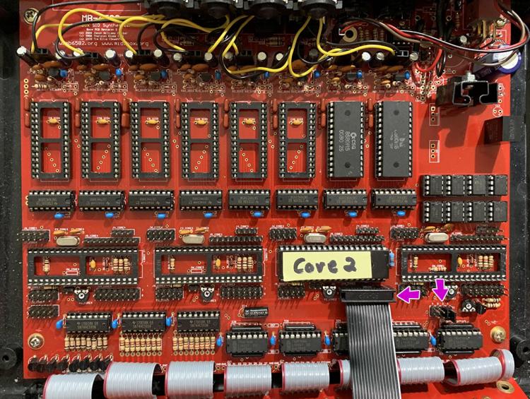
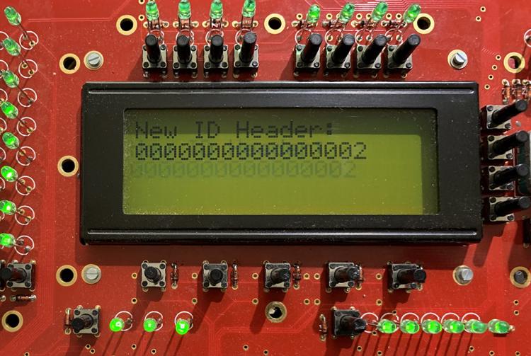
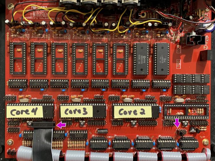
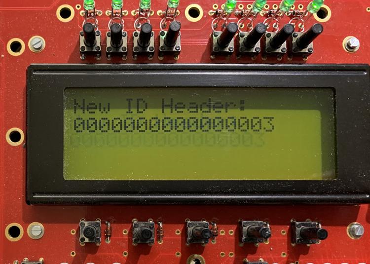
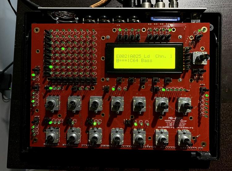
SUCCESS! My hunch panned out... So now I have all cores working properly, with the correct Device ID's... Once again, in the end the process was simple and straight forward, but easy enough to get confused with... For anyone that's interested in a step-by-step guide, here's what I did... Step 1: Write the basic bootloader to all 4 of your PICs Step 2: Place the PIC that will become the Master Core 1 into the correct Socket, launch MIOS on your computer and access it as Device 0 Step 3: Now you'll use MIOS to write the MIOS OS hex, followed by the setup_mb6582 hex. (more info for steps 1-3 here: (http://midibox.org/forums/topic/21324-change-pic-id-using-a-mac-for-mb-6582-core-0/#comment-186254) Step 4: Once you're done with Core 1, you can test your control surface navigation, listen to the default patch sound, etc... Step 5: At this stage I chose to remove Core 1. I didn't want MIOS to be confused when I added in Core 2, which will have the same Device ID 0 (not sure if this step was necessary though?) Step 6: Place the first Slave, Core 2, into its proper destination socket. You'll need to move the J11 jumper to position 2 to enable MIDI out to come from Core 2. You'll also need to move the LCD cable to J15_CORE2 so you can watch the screen through each update phase Step 7: Power up your MB-6582, MIOS should see Core 2 as Device ID 0 now. You'll change Core 2 to become Device ID 1 by using MIOS to write the 'device_id_01.hex' file that comes bundled with 'change_id_v1_9g.zip' (available in the troubleshooting section http://www.ucapps.de/mios_download.html) Step 8: Your device should reboot after you've written the device_id_01.hex. When it comes back online your LCD should show "New ID Header: 0000000000000001" - you've done it! MIOS should see Core 2 as Device ID 1 now Step 9: Go ahead and write the MIOS OS and setup _mb6582 hex files, to device ID 1, just as you did for the Master Core 1 ...Now you'll basically be repeating Steps 6-9 for each of the remaining Slave Cores... Step 10: Power down your MB-6582 and add Core 3 into its proper destination socket. Move J11 to position 3 and the LCD cable to J15_CORE3 Step 11: Power up and do the same as Step 6, using MIOS with Device ID 0, you're ready to change Core 3 to become Device ID 2. Write the 'device_id_02.hex' file you downloaded with the change_id package Step 12: When your device finishes rebooting, your LCD should show "New ID Header: 0000000000000002" and MIOS should see Core 3 as Device ID 2 Step 13. Go ahead and write the MIOS OS and setup mb_6582 hex files Step 14: Power down your MB-6582 again, add Core 4 into the proper destination socket, move J11 to position 4 and the LCD cable to J15_CORE4 Step 15: Power up and do the same as Step 6, using MIOS with Device ID 0, you're ready to change Core 4 to Device ID 3. Write the 'device_id_03.hex' file you downloaded with the change_id package Step 16: When your device finishes rebooting, your LCD should show "New ID Header: 0000000000000003" and MIOS should see Core 4 as Device ID 3 Step 17: Go ahead and write the MIOS OS and setup mb_6582 hex files Step 18: Power down your MB-6582, add Core 1 back into its lonely socket, move J11 to position 1 and the LCD cable to it's permanent home on J15_CORE1 That's it.. When you power back up you should have a full set of Master and Slave cores with all the correct Device IDs! Moving forward, you'll never need to physically touch the cores and jumpers again to update the firmware. You can simply write new firmware to Core 1 (Device ID 0), then reboot while holding down the menu button, to automatically clone to all slave cores (magic!). Word Doc with full procedure here for offline reading: https://1drv.ms/w/s!AtmSvwylfFJaggnN1TtalEzGQK1C?e=D6UJrH Cheers!


-
@Noise-Generator yet more useful info, thanks... I've been digging through so much online material that it's clearly started to clog my brain and prevent the facts from making their way in! My MB-6582 contains 8 x 8580R5's, so the ability to clone across all cores whenever a new firmware comes out, would actually be really useful. I'd prefer not to have to touch the hardware again. The piece my brain is struggling with is, at what point in the process of creating the Slave cores do they receive their unique Device ID? I have a hunch that I should have been using MIOS to apply the device specific hex files, instead of my PIC writer... I'm going to try that now... (fingers crossed)
-
I'm actually having this issue right now (almost ~5 years after this post originated ;-) I tried writing just the basic bootloader hex to each PIC, then running through the clone process (press menu button while powering on), but this fails for me every time, exactly the same way as in the original post... Following the advice here, I tried the same approach that @EsotericLabs has outlined, of burning the basic bootloader to each PIC (e.g., bootloader_v1_2b_pic18f4685.hex) then moving them, one-by-one, into the Core 0 socket in the MB-6582, so that I could apply firmware using MIOS (e.g., mios8_v1_9h_pic18f4685.hex). That process worked fine, but once I moved the PICs into their correct sockets, MIOS couldn't see them as Device ID 1, 2 or 3? In a separate thread, there's discussion of having to use "change_id v1_9g" to change the default Device ID of 0 that the PICs receive with base bootloader image. The 'change id' package even contains new hex files with names like device_id_00.hex, device_id_01.hex, device_id_02.hex, device_id_03.hex. I've tried to use these in place of bootloader_v1_2b_pic18f4685.hex, but this didn't help. MIOS can communicate perfectly with my Master Core 0, but it's unable to see any of my Slave cores over a different Device ID. BTW - I can confirm that I've been moving J11 to correspond to the Core I wanted MIOS to be able to communicate with. ...So basically, I still haven't been able to create Slave Cores. (uhg!) Any suggestions are appreciated.
-
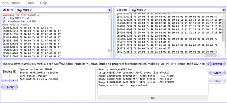
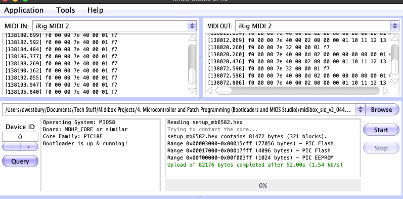
OK, OK, OK... After several days of mind bending torture, I finally figured it out... And it's actually extremely easy... DOH! Step 1: Write bootloader_v1_2b_pic18f4685.hex to the PIC using your favorite Microchip utility (I used MPLAB X IDE, others like IPE Pickit Programmer, etc.). Step 2: Load up MIOS (I'm using v2.4.9). It should detect the PIC as Device 0 (default behavior), then you can write mios8_v1_9h_pic18f4685.hex (both hex files above come from 'mios_v1_9h.zip' available in the Operating System section of the downloads page: http://www.ucapps.de/mios_download.html) Step 3: If all goes well, your LCD will show "READY." (a cute throwback to the old C64 days), then finally you can write setup_mb6582.hex Step 4: When your system finishes rebooting, it should be ready for control surface testing... Big thanks to @Noise-Generator for keeping me sane as I careened off one cliff and onto another... Wheew... Special note: I wasted a ton of trial-and-error-time time before I finally realized that I had one bad PIC in my batch. Newbie brain + fat fingers mean, I probably installed it backwards into the chip writer one too many times or maybe I exceeded its natural rewrite threshold, etc. I was always able to write the bootloader to it, but MIOS would never detect it. I didn't have enough experience with the process to realize that I was working with a dud... In hindsight, a telltale sign to remember is that every LED on the control surface was lit up when this PIC was in the Master Core 1 socket. This is what you would see if you powered up with no PIC in the Master Core 1 socket. With a properly functioning PIC, you won't see any active lights on the control surface until the setup_mb6572.hex is installed... Mentally filed under lessons learned....

-
I wrote bootloader_v1_2b_pic18f4685.hex to a different PIC (using the IDE) and was finally able to get MIOS to recognize it as Device 0. I was also able to use MIOS to write setup_mb6582.hex - Progress! However, my control surface and LCD still aren't working? - Torture!

-
First off, thanks for riding this rollercoaster with me. In the end I'm sure it's a case of "user error" ;-) I think I need to burn three hex files to get the proper bootloader ('bootloader_v1_2b_pic18f4685.hex', 'mios8_v1_9h_pic18f4685.hex' and 'device_id_00.hex'). The default behavior of the IDE is to erase the PIC before writing, so I either need to figure our how to turn that option off or somehow combine all three files together and write once? Hope I'm pointing in the right direction now ;-)
-
I thought that change id was actually using gpasm to merge multiple hex files together (e.g., main.hex + device_id_00.hex + iic_midi_10.hex, etc...)?
-
Apologies for spamming the forums today as I iteratively struggle my way through this process... I'm attempting to run 'change id' now, to generate a new hex file with the correct Device ID, but i'm a bit confused about what to edit in the 'Makefile.orig' Appreciate your patience if you've made it this far! ;-)
-
Making progress... I installed MacPorts, which enabled me to find and compile working versions of sdcc and gpasm for Mac OSX Catalina 10.15.3. However, before I attempted to run 'change id', I thought I would first try to follow the MIOS Bootstrap guide (http://www.ucapps.de/mios_bootstrap_experts.html). I hoped that a fresh PIC with the bootloader images ('bootloader_v1_2b_pic18f4685.hex' & 'mios8_v1_9h_pic18f4685.hex') would default to Device ID 0, which should be detectable by MIOS Studio. But unfortunately, MIOS 2.4.9 doesn't see my new PIC on any of the selectable Device IDs? Does this means I need to tweak Device IDs (and other settings) in the hex files, even for freshly burned PICs? Thanks...
-
Yep followed that one... Still stuck, but let me explain... The readme for 'change_id_v19g' says... Thanks much!
-
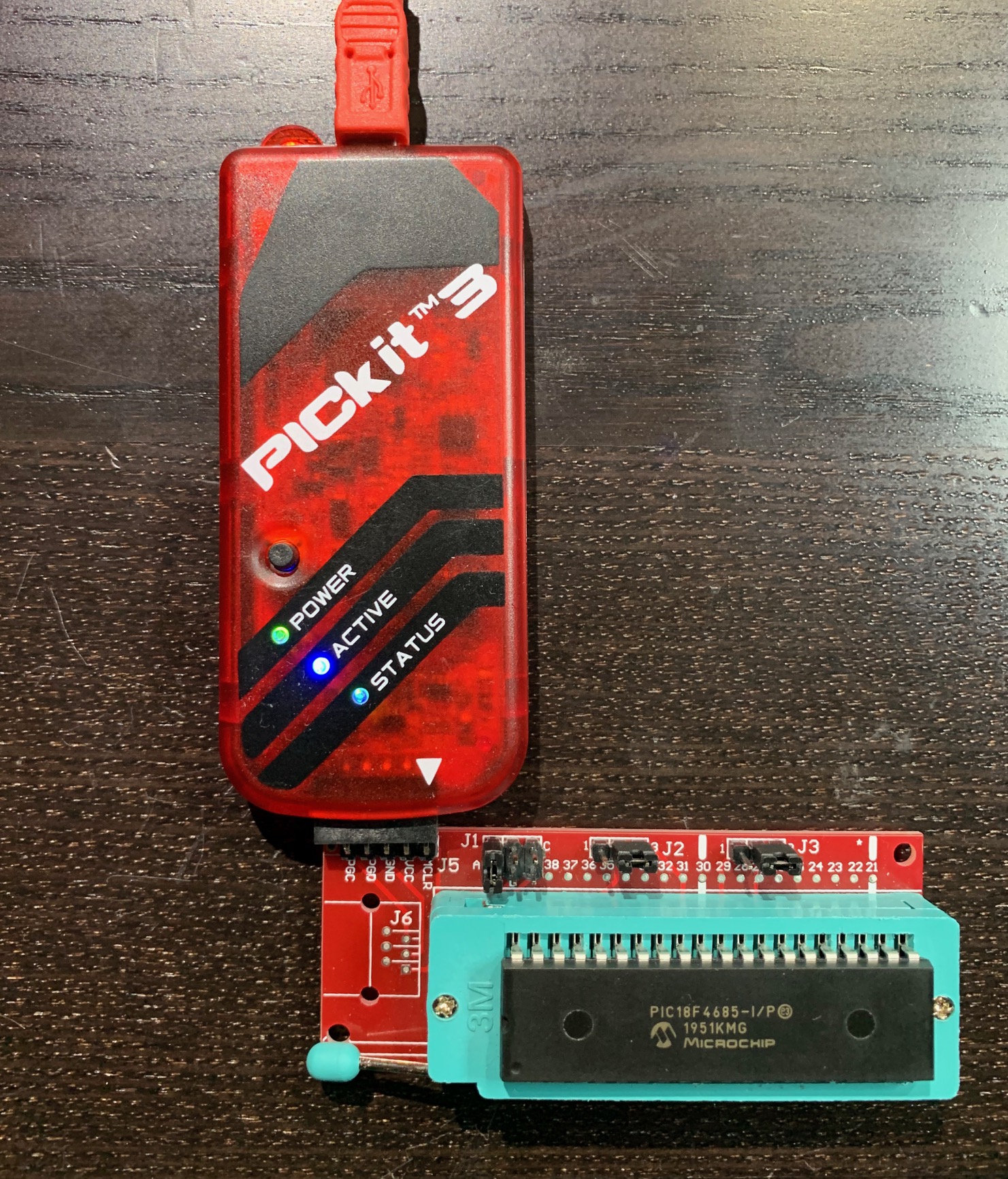
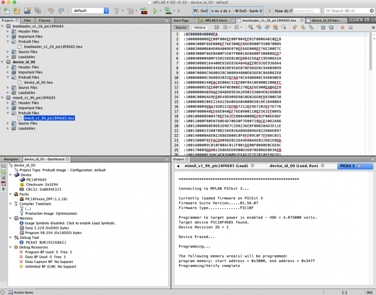
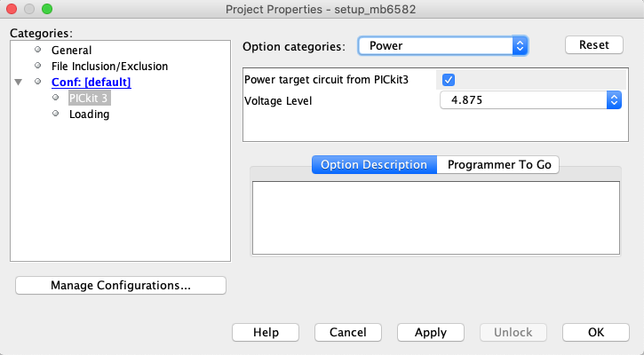
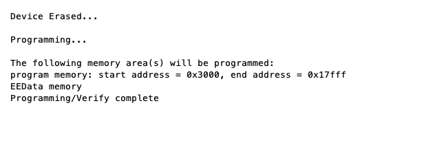
I finally got my PicKit 3 working in MPLAB X IDE. I needed to manually configure the Pickit to supply source voltage to the PIC. Interestingly it failed when I supplied 5V, but it works perfectly and consistently with a little less (i.e., 4.875V). So now I'm able to burn the setup_mb6582.hex files, which uses the memory range 0x3000 to 0x17fff, but I seem to missing the boot loader code? Appreciate any suggestions and guidance...
-
I managed to burn the setup_mb6582.hex to my PIC18F4685 using MIOS Studio (2.4.8) from my Mac, but somehow I set the Core ID wrong. MIOS communicates with the PIC perfectly on Device ID 2, but I can't boot properly or use my control surface this way! I've scoured through a bunch of the MIOS material in the Wiki and the Forums, but I can't seem to follow the steps (sorry, newbie brain is trying!). Many thanks for any assistance... Cheers