ilmenator
-
Posts
2,305 -
Joined
-
Last visited
-
Days Won
37
Content Type
Profiles
Forums
Blogs
Gallery
Everything posted by ilmenator
-
Actually, the Osh Park boards allow for very low tolerances even for traces / pins close to the board's edges, so you could probably even decrease board size some more.
-
You can cut off the legs so that they don't require holes on the PCB. However, I don't think you can cut through the body of the device without destroying the remaining resistors. But then, why don't you just try? It's a cheap item, so even if you destroy one it won't hurt too bad...
-
For that purpose you could always order a tiny little adapter board at Osh Park for reasonable money.
-
Nah, too busy building stuff - no time for making music...
-
[brokenrecord] off-site docu bad [/brokenrecord]
-
Good job!
-
Yes, I can confirm that with both versions my LCDs are working correctly, just like with the v4_070_pre1. :phone: Kind regards, ilmenator
-
I think that is highly improbable in my case, as I am using the MeanWell RPT-60B from NorthernLightX's bulk order - which supplies up to 4A on the 5V rail... One thing that I suspected was that the displays might not get enough power during the init phase, because I had added the 2200uF capacitor to the secondary side (5V) instead of putting it before the Vreg which is not used any longer. This is recommended somewhere on ucapps.de. My reasoning was that it might take a little too long to charge the capacitor, and that that would drop the voltage just long enough for the display init to fail. However, when I removed the capacitor nothing changed.
-
Beautiful - this works perfectly :hyper: . Thanks a lot! So how did you spot this one?
-
I'd rather say these many options are one of the strong points of the MIDIbox universe. Not necessarily trivial to handle at times, but definitely worth keeping and extending :yes:.
-
Sure :phone: !
-
As I have a BLM 16x4 integrated into my SEQ I have decided to switch off the GP LEDs. This is easily done in the Config file: # 0: no mapping of 8x8 LEDs # 1: enable GP LED -> 8x8 matrix mapping for Wilba's MB-SEQ PCB BLM8X8_DOUT_GP_MAPPING 0 However, also the GP buttons are not needed as trigger buttons any longer. Would it be possible to make that configurable, too, such that the GP buttons carry (by default) the functionality that they otherwise only have when holding down the MENU button? At the same time, the GP LEDs could then also be used to indicate the current menu (i.e. MIXER, EVENT, MODE,...). That should of course be obvious from the LCDs, but would add a little bling and usefulness for those LEDs. Best regards, ilmenator
-
Extended front panel design - what to do with two extra buttons?
ilmenator replied to ilmenator's topic in MIDIbox SEQ
The order placed was for 3 prototypes only and comparatively expensive looking back at the 16x4 BLM PCB. However, there are some tracks on this board that are running between the smd pads for the shift registers - I did not want to take any risk with respect to board quality. Let's discuss larger quantities once the design has been confirmed to work :smile:. At least the size of this one is much more shipping friendly than the 16x4 BLM board. -
There is a thread over at the MBSEQ section of the forum that discusses my 16x4 BLM PCB design. I have now created a Wiki entry that holds all the necessary documentation for building you own 16x4 BLM, including board schematics, Gerber files, and so on. Kind regards, ilmenator
-
For those of you that came too late to get one of my prototype PCBs (or who just discover this thread now), I have documented the board design and everything you need to know to build your own unit over in the Wiki. You'll find schematics and Gerbers there (so you can order your own boards anywhere you like), as well as the BOM and some other hints. Kind regards, ilmenator
-
I don't think we need another core module. Those with a broader knowledge in electronics will easily come up with solutions such as Duggle's. For beginners, adding more choices in terms of board variety is bad because it will confuse them even more. And supporting them will be more difficult. We do have a lot of different projects running on the MIDIbox platform. The choice of components sitting on the core board right now is actually a very good compromise. Your minimal config of 8 I/Os and 8 analog inputs is already there! Going SMD is fine for advanced users. It scares most beginners. That would call for pre-assembled boards - very problematic, we had this with the Core32 boards that had the processor pre-soldered. Using an LPC "shield" is much more comfortable and makes for potentially more successful projects IMHO. Having the MIDI connectors on the board is crucial for me. You probably don't remember the old 8bit PIC core board which used breakout cables - I am really glad we have left that era behind... That is something even your project won't solve :smile: .
-
Extended front panel design - what to do with two extra buttons?
ilmenator replied to ilmenator's topic in MIDIbox SEQ
Board has been ordered, delivery in about 3-4 weeks to my place.
-
What MIDIbox project are you having problems with?
-
Extended front panel design - what to do with two extra buttons?
ilmenator replied to ilmenator's topic in MIDIbox SEQ
You actually had me worried for around half an hour until I discovered that the upper and the lower part of my breadboard's vertical power rails are not internally connected, leaving the last shift register in the chain floating, which resulted into VERY strange effects... :shocked: -
No, because that is a clean and stable 5V that can be fed directly into the core board's components. I am doing that on my SEQv4.
-
Extended front panel design - what to do with two extra buttons?
ilmenator replied to ilmenator's topic in MIDIbox SEQ
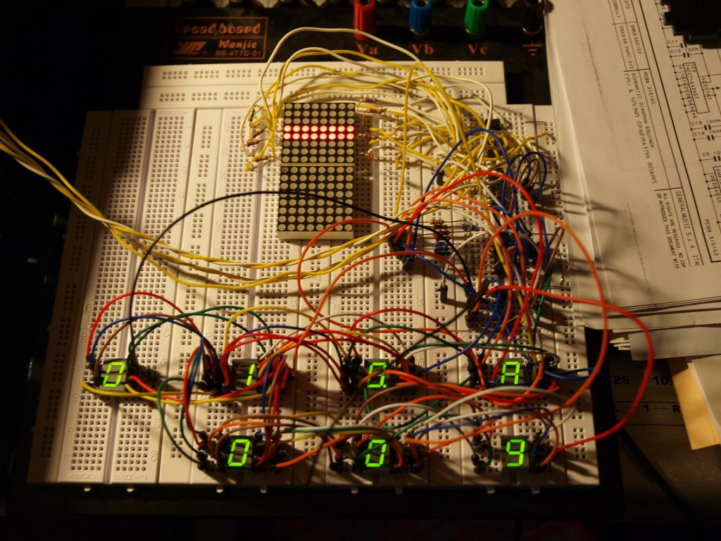
So I checked the official BPM schematic for pinning and brightness, and the results are very promising. BPM and STEP segments are connected to the same shift register, and the brightness is totally acceptable using 220Ohm resistors and 7 Kingbright SC39-11 type 7-segment displays all at once, with no additional drivers. Brightness is obviously increased somewhat by using 100Ohm resistors instead, I did not test lower values than that. If you look closely you might see that when taking the picture I was using 220Ohm resistors for 4 segments (including the dot) and 100Ohm for the other 4 segments. However, that is a (visually) small difference. I'll place my PCB order soon, I'll pass on one of the boards to Hawkeye for software mods of the TPD matrix.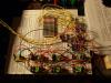
-
Extended front panel design - what to do with two extra buttons?
ilmenator replied to ilmenator's topic in MIDIbox SEQ
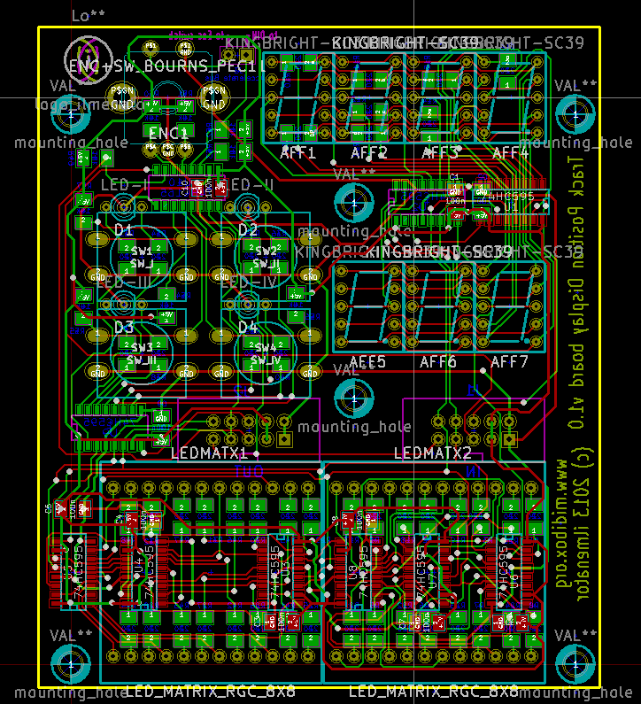
I am not sure the ULN drivers make any difference at all. There was some discussion over in the LED ring board thread, but I don't think there were any definitive conclusions on whether they would help the LEDs brightness or not. As the limiting factor seems to be the duty cylce and not the driving current, I doubt that the ULNs would make a difference here. Also, as you can see from the image above, this board is really short of remaining real estate for placing even a single ULN. I'll check how the Kingbrights behave, though, and think about alternatives if necessary. Best, ilmenator -
Extended front panel design - what to do with two extra buttons?
ilmenator replied to ilmenator's topic in MIDIbox SEQ
ok, I have received the Reichelt order today and will take the stuff with me when returning home tomorrow. I'll do testing next week, so the time frame for receiving the boards would be 4 weeks from then. No arctic snowballs :-). -
Extended front panel design - what to do with two extra buttons?
ilmenator replied to ilmenator's topic in MIDIbox SEQ
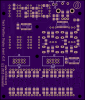
After a weekend of trace tetris I have a board design. It's a bit crowded there and not for the shy :pirate: . Harrrrr. Now I wonder if I need to test the official BPM display schematic like Hawkeye suggests or not? TK?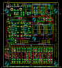
-
Extended front panel design - what to do with two extra buttons?
ilmenator replied to ilmenator's topic in MIDIbox SEQ
Thanks Peter! That I have obviously done already - a few months have passed, so there was time for this. Also, I suspect that the pinout for the LED matrixes is not the same with every brand, and even the data sheet I got for mine was wrong. Great, so the jumper/connector is sitting on the right end of the switch. For the LED digits I am simply following the official schematics. That has been done - obviously I am not going to shell out money for a PCB that is based on schematics that have not been breadboarded. I was rather looking for comments on changes that might make your life as a programmer easier. Apparently there are no such proposals, so I'll just go ahead :smile: . Best, ilmenator