ilmenator
-
Posts
2,305 -
Joined
-
Last visited
-
Days Won
37
Content Type
Profiles
Forums
Blogs
Gallery
Everything posted by ilmenator
-
Display Connection with Mirrored Pinout
ilmenator replied to novski's topic in Testing/Troubleshooting
Did you have your scrambled display hooked up to the inversed voltages? That might explain a garbled screen and a dead first row... -
Without the proprietary Ploytec firmware these chips are obviously dumb. They can only be obtained from Ploytec, and in large quantities. If there is enough demand, TK might consider a new bulk order some time in the future. If I remember correctly, we are talking minimum quantities of 250 pieces here.
-
Welcome here! For the MIDIbox part of the controller universe, you might want to look at the MB NG. It runs on the LPC17 core (much more powerful than the PIC core used in the Chaos Matrix) and can be configured to handle SysEx messages rather easily. Storage is done via SD cards. It is surely going to be more expensive than a used BCR2000, but you will be able to configure it exactly as you want. Do some reading and come back with more detailed questions here. Good luck, ilmenator
-
I still have some ALPS jog/shuttle wheels left, for details see Preferably to people within Norway, as otherwise shipping costs might be too high - though I would have to check in case there is interest. Best regards, ilmenator
-
Extended front panel design - what to do with two extra buttons?
ilmenator replied to ilmenator's topic in MIDIbox SEQ
Another update: after modifying the board and double-checking that a) the PCB's design was according to Hawkeye's datasheet and b) the breadboard cabling was exactly as on the PCB design, I still got the same behavior. Puzzled? So was I... Turns out that apparently they sold me what seems to be common anode LED matrix modules instead of common cathode ones - that's the drawback of buying at Chinese ebay-shops: you don't always get what you want. It also explains why "the other color" is always on... because if a DOUT SR is not explicitly set to 1, its output should be 0, sinking what I thought would be the common cathode (but is common anode instead). Fortunately, that should not be a big deal with matrix designs, as I would assume that all I need to do is invert the state of all output shift registers involved and I'm done. Hawkeye, could you give me a hint where in the code this might be done? Best regards, ilmenator -
Extended front panel design - what to do with two extra buttons?
ilmenator replied to ilmenator's topic in MIDIbox SEQ
Well, turns out my datasheet was wrong and Hawkeye's is right. Even though I tested on breadboard, I never had both colors connected to shift registers at the same time - though I probably should have... A new protoboard will be ordered, I am not going to wirewrap this... -
Gold Phoenix will usually send you a quote after you have uploaded the Gerbers. Whatever you enter in their form is just for giving you quick online feedback, I believe. 16x16mm in the Wiki is indeed an approximation, yes. I believe that is actually the recommended opening in the frontpanel - it's in the cap's datasheet.
-
Extended front panel design - what to do with two extra buttons?
ilmenator replied to ilmenator's topic in MIDIbox SEQ
I'll check this - at first sight the pin out does look different from what I seem to remember, but I'll look at it tonight. In case it's different I'll send you two of mine. -
Yes, but that was after I had desoldered mine already :smile:.
-
Extended front panel design - what to do with two extra buttons?
ilmenator replied to ilmenator's topic in MIDIbox SEQ
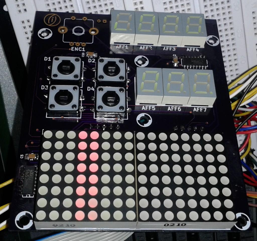
Boards have arrived (pretty fast this time!), and of course I managed to mess up the segment order on the 7-segment displays... So there will be some wire wrapping tonight to get it right again. The strange thing is that it WAS working okay on my breadboard, but apparently I got it wrong when transferring that to PCB - probably because I got confused by the DOUT module's pin numbering. I think that is one of the most effective pitfalls that MIDIbox has to offer :rofl: . The other interesting thing is that in the 8x8 duo LED matrix, the "other" color is always on, presumably because the corresponding shift register is not properly set, as it is not defined in the config file (yet). Oh, and sorry for s****y phone camera picture. In real life the colors / brightness are totally okay :smile: .
-
That is a really, really good price - I desoldered mine from old (but actually mostly unused) equipment, I think I wouldn't have gone through the hassle had I known about this supplier earlier! The "feel" of these is superb. Thanks for providing that link, freddy!
-
TK wrote This is for four of the LRE8x2 boards, LPC 17, and an LCD without backlight. Add the motorized faders to the equation (not sure how much they would consume, do the search yourself) and you know what you want.
-
Na fuer das Geld kann man doch nicht meckern - ich finde die Farbe ok :smile: .
-
Ok, these would be e.g. Reichelt part WSL 10G.
-
You mean Wilba's control surface design? It's over in the WIKI.
-
Hi, I need the service manual of any of the Mackie MCU Pro units (i.e. either Mackie Control Pro, Control Extender Pro, or C4 Pro). The magic smoke appeared and I need to check what parts are still functional... Thanks, ilmenator
-
Eben. Deshalb ist es ganz gut wenn du selber mal mit einem Durchgangstester prüfst, wo die einzelnen SD-Card-Kontakte hingehen. Das ist bei dieser Platine ganz einfach möglich, weil die Lötpads des Kartenhalters frei liegen. Du willst doch nicht dass wir aus versehen falsch raten und du deine Karte zerstörst, oder? :devil:
-
Hier kannst du nachschauen welcher Pin der SD-Karte mit welchem Pin auf der LPC-Platine verbunden werden soll. Die +5V kannst du ignorieren.
-
Auf ucapps.de gibt es fuer jedes Modul eine Reichelt "orderlist" - trotzdem wirst du auch selbst noch ein wenig Zeit und Arbeit investieren muessen um das zu pruefen und ggf zu korrigieren bzw. in die Maske auf der Reichelt-Seite einzutippen. Falls dir das zu umstaendlich ist kannst du einfach ein Kit bei SmashTV kaufen. Die Gretchenfrage ist halt wie wertvoll dir deine eigene Zeit ist :whistle: .
-
Ich zitiere mal aus der Artikelbeschreibung: "Weitere technische Angaben sind zur Zeit nicht möglich!" --> was sollen wir da an Tips geben? Meine Nase sagt mir: wird schon passen, aber das Risiko ist immer noch deins :smile:
-
Yes, there is a good chance that these displays will work. You can find the datasheet here and if you search around a bit you will find that the display controller is pin compatible to the Hitachi one. The only thing that might get in the way is different timings - however, that risk is rather low.
-
I understand - thanks nevertheless!
-
No, I am not using this - in other words, my setting is # set this to 1 if these buttons should only control the "step triggers" (gate, and other assigned triggers) - and no UI functions BLM_BUTTONS_NO_UI 1 because my understanding of workflow would be that the BLM buttons are exclusively meant for triggering, whereas the (former) GP buttons are exclusively meant for menu handling. And even if I set this parameter to "0", what happens is that I then end up in SYS EX mode, the same as if I was pressing the GP16 button. That actually makes sense to me :smile: . Yes, I totally understand that!
-
No, that simply switches the 16th "note" in G1T1 on or off, depending on the previous state. Ok, it seems that # 0: no mapping of 8x8 LEDs # 1: enable GP LED -> 8x8 matrix mapping for Wilba's MB-SEQ PCB BLM8X8_DOUT_GP_MAPPING 0 simply switched the LEDs completely off - I have set that back to 1 and now they light up as expected :smile: , albeit pulsating. However, then I also get the red LEDs running across when the SEQ is started, something that I wanted to avoid :sad: .
-
Thanks! There are a few things that do not work as expected with this mode set to "1": I guess there are a few dependencies that got lost along the way? The simplest example: in EVENT mode, when I try to change from "Note 128..." to e.g. "Note 64..." I am asked to initialize the track. However, I can't do that by turning the last GP encoder, and pressing the GP button number 16 now obviously takes me to the SYS EX mode. I am not sure I have just opened a can of worms here? If this is an "easy" fix and you are willing to keep this mode, can I also suggest to have the respective LED, e.g. the green one, being switched on while in one of the modes directly accessed by the GP buttons, and switched off again when back in EDIT mode? Best, ilmenator