ilmenator
-
Posts
2,305 -
Joined
-
Last visited
-
Days Won
37
Content Type
Profiles
Forums
Blogs
Gallery
Everything posted by ilmenator
-
It might depend a little on the manufacturer, but a general procedure would be to use ground meshes instead of solid planes. You can find a fine example of this on the LPC17 board. And I stand corrected, apparently heating up the whole board and letting it cool down as per the link you provided seems to cure the problem. Maybe using a heat gun if you don't have a rework station is feasible, too?
-
Extended front panel design - what to do with two extra buttons?
ilmenator replied to ilmenator's topic in MIDIbox SEQ
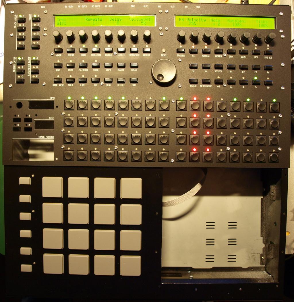
It's been a long time since I have started this. Well, in the meantime I got my "box" mechanically ready to house the SEQ and the BLM, now it is time to design the TPD board. Peter, could you please take a look at the attached schematics and check for any obvious errors? All LEDs are common cathode types. I could not find infos on the external "push-to-accellerate" bus you mentioned above, how would that work? Is the schematic compatible with what you have in mind? Also, I would assume that pins are freely configurable in software, but if you think it would be easier/faster to implement anything with a different pinout then that should be changed now :smile: . Thanks, ilmenator TrackPositionDisplay_schematic.pdf -
Question about hooking up KS0107/KS0108 GLCD
ilmenator replied to grizz's topic in Testing/Troubleshooting
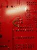
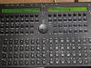
That should not be a problem here. What happens on that board version is that the 5V pin is directly connected to R33, so as long as you are using a 5V display you are fine. It's a little problematic if you ever try to connect a 3.3V display, though :-). I have added a picture of the modification to -
Thanks for your input, Tim. But the polarity of R33 is fine, as well as its value. I even measured the individual resistances, all good. This is a v1.0 board that had a wrong trace between the 5V pin of J15_S and the common pin of R33, but that has been fixed with a trace cutter and a short wire between the middle pin and the common pin of R33. It is now exactly as in the schematic. Edit: added picture of the modification.
-
It's a 74HC595 on both boards. I guess I'm just giving up on this and use the Core32 - I am probably never using OSC after all, so I could better spend my time starting with the design of the TPC board instead. There are some holes in my front panel that need to be filled... I know it's kind of lame, and usually I would want to find out why things are happening the way they do (I guess engineers have a tendency to do this), but here I'll just go for the easy fix. There are more issues to solve along the way with this box :-).
-
That usually happens when there is a large ground plane on one side of the board and none on the other, and the board is above a certain size. There is nothing you can do about it, except revise the design for the next run of boards.
-
Control surface PCB for 16 encoders/LEDrings Bulk Order
ilmenator replied to Fairlightiii's topic in Bulk Orders
As interesting as this discussion is, I think if you want displays that sit on top of each row of encoders (however many characters they display) you will need to design a new PCB. Fairlightiii's PCB was done with a different usecase in mind - no displays at all - which it is perfect for. I would therefore suggest to continue discussion of this in a separate thread. -
Control surface PCB for 16 encoders/LEDrings Bulk Order
ilmenator replied to Fairlightiii's topic in Bulk Orders
You are not seriously demanding that folks here create a facebook account to see these pics??! The proper way is to upload pictures here. Edit: thanks for editing your post! -
I can set all data lines to "1" manually, and individually. However, whenever I issue a set command to any other data line, the one that was previously set to "1" goes to "0" again - i.e. there is only ever one single data line at "1" simultaneously, all others are always "0". Is that how it is supposed to be? Edit: Also, I just checked the LPC17 board for shorts - it is good, no shorts, and all connections are there, as they should be. I also exchanged IC2 (the 595), but nothing has changed. Unconnecting one display from the cable does not help either. Only if I unplug one cable from the LPC17 core board, the remaining display works fine. One cable is about 25cm long, the other about 45cm. As the cables and displays are the same as for the Core32 board I really don't know what could be the problem.
-
[19343.834] testlcdpin rs 0 [19343.836] J15A.RS and J15B.RS set to ca. 0V [19376.329] testlcdpin d7 0 [19376.331] J15A.D7 and J15B.D7 set to ca. 0V [19376.332] D7 input pin correctly shows logic-0 [19401.689] testlcdpin d7 1 [19401.691] J15A.D7 and J15B.D7 set to ca. 5V (resp. 3.3V) [19401.691] D7 input pin correctly shows logic-1 [19422.440] testlcdpin d6 0 [19422.442] J15A.D6 and J15B.D6 set to ca. 0V [19422.442] D7 input pin correctly shows logic-0 [19430.008] testlcdpin d6 1 [19430.011] J15A.D6 and J15B.D6 set to ca. 5V (resp. 3.3V) [19430.011] D7 input pin correctly shows logic-0 [19462.688] testlcdpin d0 1 [19462.690] J15A.D0 and J15B.D0 set to ca. 5V (resp. 3.3V) [19462.690] D7 input pin correctly shows logic-0 [19471.711] testlcdpin d0 0 [19471.713] J15A.D0 and J15B.D0 set to ca. 0V [19471.713] D7 input pin correctly shows logic-0 [19552.046] testlcdpin e1 0 [19552.048] J15A.E set to ca. 0V [19587.157] testlcdpin e1 1 [19587.159] J15A.E set to ca. 3.3V I'm not exactly sure what I am supposed to test here. I can set pins high and low, but am I supposed to measure on the pins directly?
-
The self-built binary (4.070) shows exactly the same behavior.
-
I'm using the v4.069 binary.
-
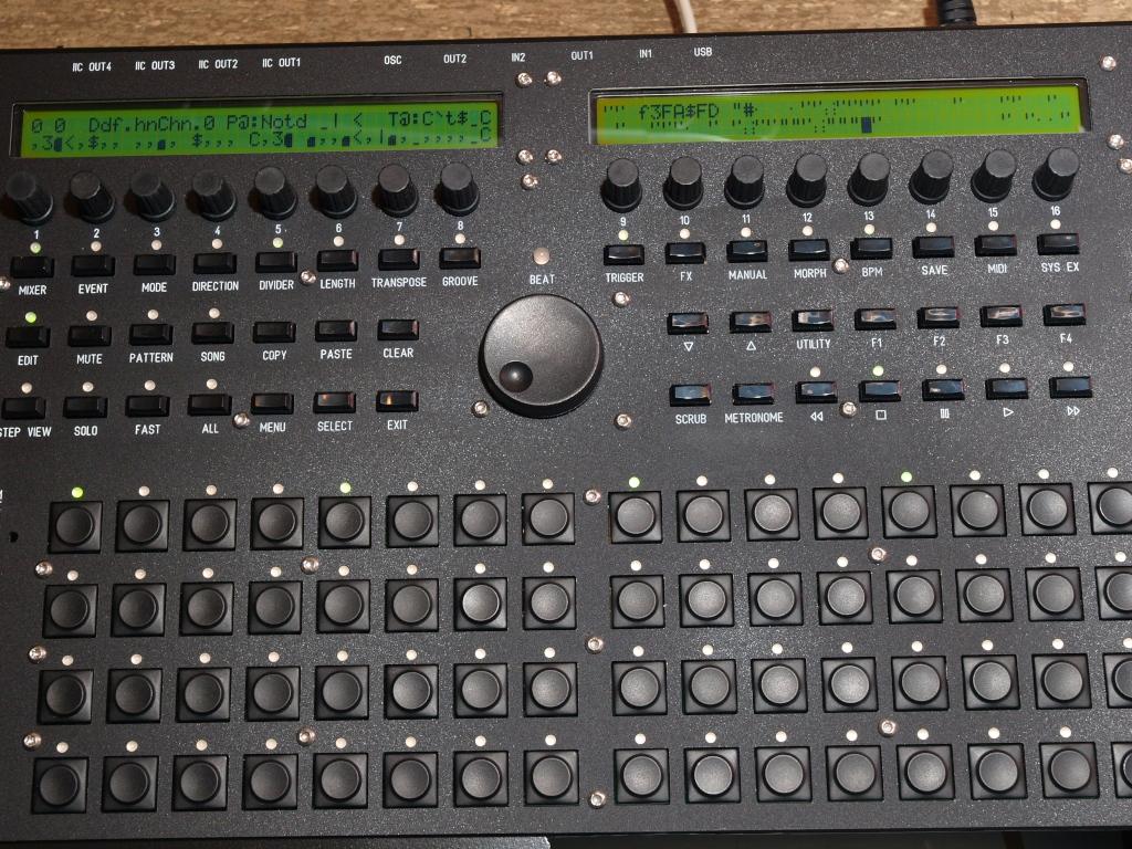
Hi, I have a rather strange (?) problem with the two displays in my MBSEQ. I tried to exchange the STM32 core with the LPC17 one, and now it seems that the initialization of the two displays goes wrong. I get garbled screens, sometimes just a few letters are wrong, sometimes there is nothing at all on the screens. When I disconnect one of them, the other is fine - this holds for both, the left and the right display. When I switch back to the STM32 core, both displays work as they should. My PSU is beefy enough, it's a Meanwell RPT-60B. Any ideas? Thanks, ilmenator
-
Well that's a 3x4 matrix actually, but what is it that you are trying to do? Simulate key presses with a MIDIbox?
-
What Parts will i definately need for a usb midi controller?
ilmenator replied to eden's topic in Parts Questions
I can only second that. DIY is not going to be cheaper than a commercial product if you are just starting or want this thing to look good. However, it's a lot more fun :-). -
No problem, just go ahead. Before doing that, you might want to read the SammichSID build guide?!
-
SELLING: ALPS Motorfaders, ALPS Encoders, Midibox CV, GM5 Interfaces, etc.
ilmenator replied to snykehd's topic in Fleamarket
I saw that as well, but Pollin is sold out... More noteworthy is the fact that the footprint is different from the Bourns encoders, and that the shaft length is 5mm shorter. That needs to be considered before buying! -
Question about hooking up KS0107/KS0108 GLCD
ilmenator replied to grizz's topic in Testing/Troubleshooting
Can you post a link to the datasheet or attach it here? -
What do you think about this Arduino DSP project
ilmenator replied to SiliconHeaven's topic in Miscellaneous
Assembled boards with through-hole components? That just doesn't make sense, sorry. -
Replace fadercontrollers in Digidesign Control 24 with MBHP_MF_NG´s
ilmenator replied to Teig1's topic in MIDIbox HUIs
I guess that should read "provides 4 separate MIDI ports via USB" :-)! -
Replace fadercontrollers in Digidesign Control 24 with MBHP_MF_NG´s
ilmenator replied to Teig1's topic in MIDIbox HUIs
Alternatively you could just use a GM5x5x5 to collect the MIDI I/Os and convert that into a single USB cable. There was a bulk order recently, maybe someone has spares? Edit: unless you do some programming, novski's setup still only gives you 24 faders on the same MIDI port. For Protools that is in no way different from chaining the three MF modules and hooking them up via MIDI proper. -
The lighter side of the MB-6582 - audio examples
ilmenator replied to Blatboy's topic in MIDIbox SID
Above the Purple Planet is epic... I dig it :heart: ! -
You're good as long as you do it the same way on both ends. To do it exactly right: there is a little triangle on each connector that indicates pin 1 - that should attach to the colored first lead of the ribbon cable (in case you are using the standard grey one).
-
Replace fadercontrollers in Digidesign Control 24 with MBHP_MF_NG´s
ilmenator replied to Teig1's topic in MIDIbox HUIs
Hello and welcome here! Yours sounds like a very interesting project - and definitely worthwhile. Avid has been a pain to deal with ever since, and they have a long history of dropping support for end-of-life products always too soon. Been there, and then turned away from them. The MBHP_MF_NG modules can be operated stand-alone. You can use MIOS Studio to configure each of them separately, and then connect them to your MIDI host. Your host will then have to talk to them over separate physical MIDI ports, one for each group of eight faders. There is also a merger available in each of the MF_NG modules, so yes, you can also chain them into one MIDI chain. Whether this is supported by the HUI protocol is beyond my state of knowledge, though! To be clear about this: you do not necessarily need a(nother) core module (there is a "tiny" 8-bit core/CPU on each MF_NG module) to get your faders operational. However, if you plan to replace the remaining innards with MIDIbox components, that will be the way to go. The LPCXPRESSO is the processor board that sits atop the 32-bit core board which is usually referred to as the LPC17 board. LPCXPRESSO is kind of a "shield" that must be purchased separately, and which contains the CPU. It saves us from having to solder SMD components. The MagJack is a network cable connector with integrated LEDs - it is soldered to the LPC17 board and can be left out if you do not want to use OSC. Where in Norway are you located? If that is close to Trondheim, pop in for a coffee and we can discuss if you have more questions! Best, ilmenator -
Nimm einfach ein breiteres und trenne es auf!