nILS
-
Posts
4,314 -
Joined
-
Last visited
-
Days Won
4
Content Type
Profiles
Forums
Blogs
Gallery
Everything posted by nILS
-
ground planes
-
dB Live - Update and (finally) some photos - update
nILS replied to DavidBanner's topic in MIDIbox HUIs
What are those nice illuminated buttons you used? Please tell me they're MECs :D -
OMG :o The caps are evil...
-
It sure is pretty and techie with all the graphics going on on the panel, but I'm not sure if I'd be able to find the right knob/button while tweaking ;-)
-
dB Live - Update and (finally) some photos - update
nILS replied to DavidBanner's topic in MIDIbox HUIs
Oooh! That's the prettiest thing :D Keep it up dB! -
Hehe, I looked it up and have to say - absolutely. Those bastards!
-
Inside the Waldorf - Q+(Customized; Wood & OLED :) + pics & chip specs...)
nILS replied to Artesia's topic in Miscellaneous
Nice job - especially the wood work :D -
Nur die Boards sollte reichen.
-
* Welches Board verwendest Du? * Von Smash, von Mike, Lochrasterplatine? * Welche Revision? * Hast Du mal ohne ICs drauf alle Pins paarweise auf Durchgang geprüft? Vielleicht versteckt sich ja irgendwo eine Brücke. Mach doch mal ein hochauflösendes Foto und lad das hier hoch - das könnte durchaus schon helfen!
-
Welcome aboard :D Would you mind sharing where you found the answer in case someone else has the question?
-
TK: Kein Problem - ist alles unter Kontrolle, wir arbeiten grad live im Chat dran ;-)
-
<----- There you go jimp!
-
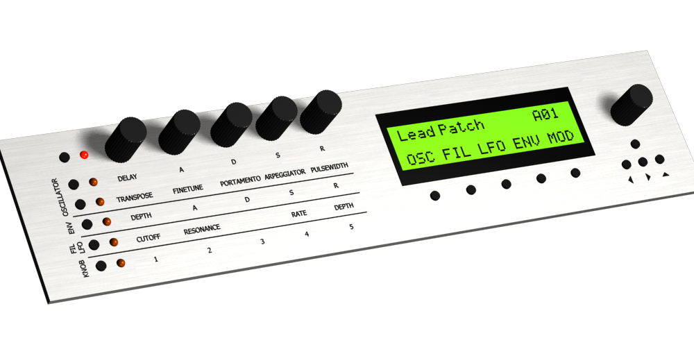
Okay, I dug out (and upgraded) the old design I was talking about in the chat earlier. Not as hip as yours but still nice ;-) I didn't create this because I wanted a big-ass quad box back then :D Here's some problems I assumed I'd encounter and some of the thoughts I had, some of which might be relevant to you as well: * implementing the layer function is fairly simple (whee!) * it would be nice to jump to the oscillator menu page if the OSC layer is activated (easy as well) * you don't really have an OSC layer though. You have a combined OSC/FILTER layer. Which means it won't work like that (you can obviously still jump to the menu page when a value is changed). I ran intop the same challenge with the combined Filter/LFO section * as wilba pointed out, aligning the encoders with the LCD would be nice.

-
Looks really good :D Some ideas from my side (might be biased as hell from all the working on the sidLive): * add a LED for the Layer-Layer * as TK pointed to me, an ensemble up/down button is pretty annoying to get through 128 ensembles * replace it with one button, which would serve as a shift button - hold it down and spin the menu encoder to change ensembles * the up/down arrows are off-center ;-) * the section right to the LCD isn't aligned with the two knobs (the cutoff, resonance ones) What remaining space? It's full. Don't add anything major anymore or it'll ruin the minimalistic-factor ;-) So far, definitely possible :-)
-
Um, this sounds pretty weird ;-) I'd try the following: 0) Leave the 12V for the SID alone for now (remove it, hide it somewhere) 1) Remove all ICs 2) Do voltage check on the core with nothing connected to it 3) On the SID board is should be fairly ease to see, which of the lines of J2 is Vss (GND) and Vdd (+5V) - Just trace the pins to the ground plane and the power pin of some IC. Just connect those two lines. 4) Do voltage check on SID. 5) Tell us what's the result :D
-
Soweit schon recht hübsch ;-) Die Encoder sind allerdings sehr nah beieinander. Steck da mal Knöpfe drauf und versuch die zu bewegen - könne recht eng werden. Ich würde außerdem lieber ein 40x2 Display nehmen (doof, jetzt haste ja schon das 4x20), da dass a) unterstützt wird und Dir b) die Möglichkeit gibt fast alle Parameter ohne scrollen zu erreichen.
-
Whee! It's working! Thanks so much stryd! I'll upload a little audio/noise file soon. EDIT: It didn't work right away for 2 1/2 reasons: * I noticed the first one while soldering the board - although the schematic looks correct, there's a missing junction, which Eagle didn'T notice either -> J1:SO( 8 ) was not connected to IC:/CS0(30) * I had an error in the source code of the SR handler (which is a C port of TK's mbSid v1.7 source) * I had to manually write to the register using MIDIOx as the software doesn't do much yet - and I for some reason sent volume "0", so it wasn't really that surprising no sound would come out of the Pokey ;-) I'll upload the updated schem and board layout as well as the software later on so whoever want's to get started on building one can do so. more edit: Removed accidental smiley :D ( <- this one is intentional)

-
Yes and no. The pokey will play about 4-6 octaves rather accurately. The tuning in some ranges of notes is a bit off due to the divide-by-N counter used for frequency generation.
-
Um, yes, this is what a pokey sounds like when you push random values into the registers - not quite my goal though :-/
-
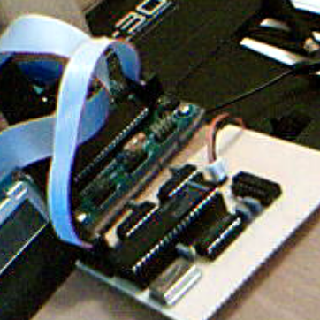
Tonight, I finished soldering the first mbPokey module. While doing so I found a mistake in the schem and the PCB layout - SO wasn't connected to the POKEY. Which is bad :D I'll check the module again tomorrow and see if I manage to get it to make some noise. EDIT: I won't be posting pics, as I don't have a digicam handy and it doesn't look all that amazing :D
-
As I've been spending quite some time looking for companies that do silkscreening for small runs (for the sidLive panel), I'm really excited to read that :D It would be awesome if you could post some close-ups of the panels you've done so far.
-
MIOS 1.9 will run on the 452. mbSID v2 won't. mbSID v1.7303b will. Make sure you upload the .hex file in the "pic18f452" folder of the MIOS download.
-
On my BOSS GT3 theres a piece of plastic mounted to the back of the panel which holds the encoder in place (see attachment). Works really well.

-
Funktioniert, hab die bei mir auch verbaut.
-
Erstmal Glückwunsch zur laufenden MIDIBox! :D Das "F0 00 00 7E 40 00 01 F7" ist der Upload-Request, der bei installiertem MIOS einmal innerhalb der ersten 2 Sekunden nachdem die MIDIBox angeschaltet wurde gesendet wird (oder werden sollte). Wenn bei Dir der request alle paar Sekunden kommt und sonst nichts mit der Box anzufangen ist bis das aufhört, klingt das, als ob Deine Box regelmässig neu starten würde. Dieses Problem kann von einem Wackler (besonders gerne am PIC selbst - einfach mal den Finger beim Anschalten drauf drücken), instabiler Stromquelle oder ähnlichem kommen. Wenn nichts davon der Fall ist, such mal hier im Form, da dieser Fehler wie gesagt schon ein paar Mal aufgetreten ist.